Timepiece containing a locking device for a pusher

a technology of timepieces and pushers, applied in the field of timepieces containing locking devices for pushers, can solve the problems of affecting the aesthetics of watches, affecting the use of watches, so as to achieve the effect of less cumbersomeness, less inconvenience, and convenient us

Active Publication Date: 2020-07-28
OMEGA SA
View PDF10 Cites 3 Cited by
  • Summary
  • Abstract
  • Description
  • Claims
  • Application Information

AI Technical Summary

Benefits of technology

[0009]The aim of the present invention is to address the various disadvantages of the prior art by proposing a timepiece equipped with a locking device for at least one pusher which is less cumbersome, more discreet and easier to use.
[0015]According to another advantageous embodiment, the pusher contains a head and the blocking means is adapted to be positioned, in order to lock it, at a short distance from this head or bearing against the latter.
[0020]According to another advantageous variant, the locking device contains a visual means facilitating the recognition of the position of the blocking means.

Problems solved by technology

These locking devices exhibit a plurality of disadvantages, however.
Since the pusher is surrounded by a coaxial control ring which must be capable of being rotated by a user and must therefore extend sufficiently radially beyond the peripheral surface of the case middle of the watch case, this pusher must be protruding while also having a short travel, which makes its actuation more difficult and less precise.
In order for the travel of the pusher to be elongated in such a way as to exhibit a usual length, the rod of the pusher must be elongated in such a way that the head of the pusher is then relatively remote from the case middle, which changes the aesthetics of the watch adversely.
Furthermore, the screw thread utilised to transform the rotational movement into translational movement must be sufficiently small for the transformation not to be reversible in an accidental manner, that is to say any friction must be sufficient to withstand unintentional unscrewing.
For watches containing a plurality of pushers, as is generally the case for those equipped with a chronograph, the locking operation may thus prove to be particularly time-consuming, since it must be performed successively for each of the pushers.
This embodiment possesses a first disadvantage due to the fact that the rear part of the head of the pusher must be inserted into the case of the watch when the pusher is in its rest position (pusher not actuated).
A second disadvantage derives from the fact that the pusher is locked by a small abutment acting solely against the upper part of the head of the pusher.
A third disadvantage arises from the fact that the locking device is cumbersome, in particular the framework which moves vertically in the case middle, which case middle must exhibit a recess for this purpose.
This embodiment with small component parts that are difficult to assemble is complicated.
The system is therefore cumbersome.
This is made even worse by the fact that the piston describes a vertical movement in order to lock the pusher, which requires a relatively large height of the case above the pusher.
The incorporation of the pusher with the piston into the case is difficult, furthermore.
In particular, the pusher itself must be assembled before or simultaneously with the two above-mentioned bezels, and it is not possible to change it subsequently without dismantling them beforehand.

Method used


Image

  • Timepiece containing a locking device for a pusher
  • Timepiece containing a locking device for a pusher
  • Timepiece containing a locking device for a pusher

Examples


first embodiment

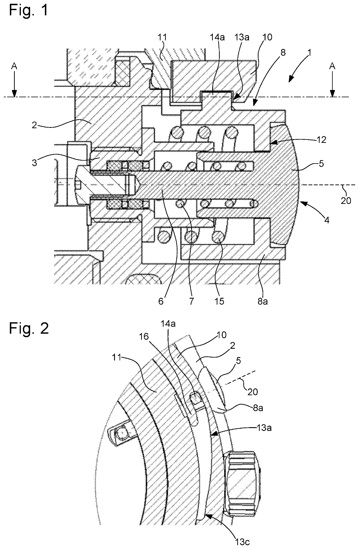
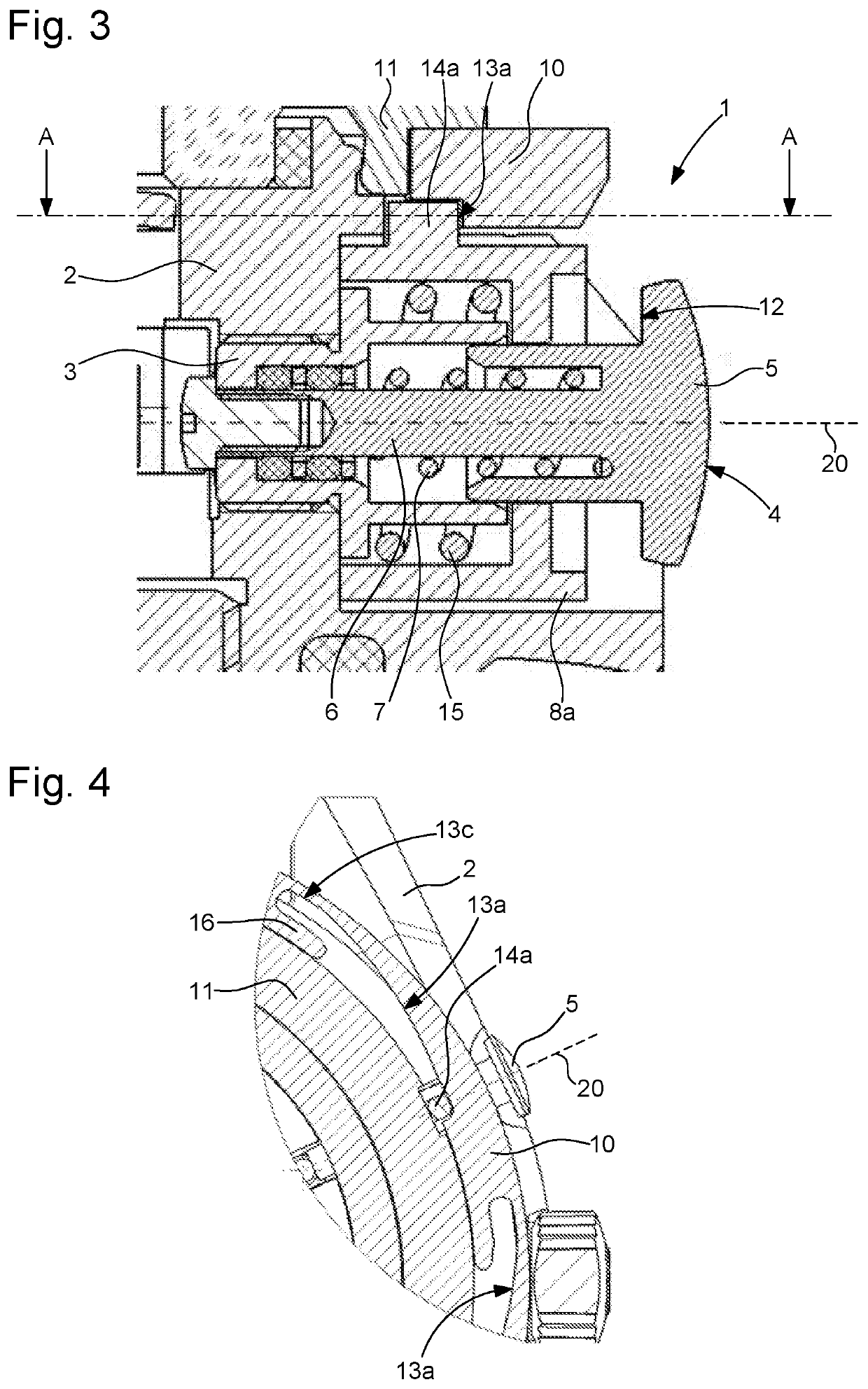
[0027]the invention is described below with reference to FIGS. 1 to 4. The figures represent partial views in cross section of a timepiece showing a push-button arranged in the case middle 2 of the case 1 and its locking device. The push-button forms in particular a control means for a chronograph mechanism. This push-button is composed of a pendant 3, screwed into a tapping that the case middle 2 contains, and a pusher 4 extending partially to the exterior of the timepiece in order for it to be capable of actuation by a user. The pusher 4 contains a head 5 and a rod 6 adapted to slide in an opening that the pendant 3 contains in an actuation axis 20 passing through the case middle in parallel to the general plane of the case. A first spring 7 seeks to maintain the pusher 4 in a distal position with reference to the case middle 2 (as represented in all the figures).

[0028]The timepiece contains a locking device comprising a blocking means 8 that is movable in a translational manner i...
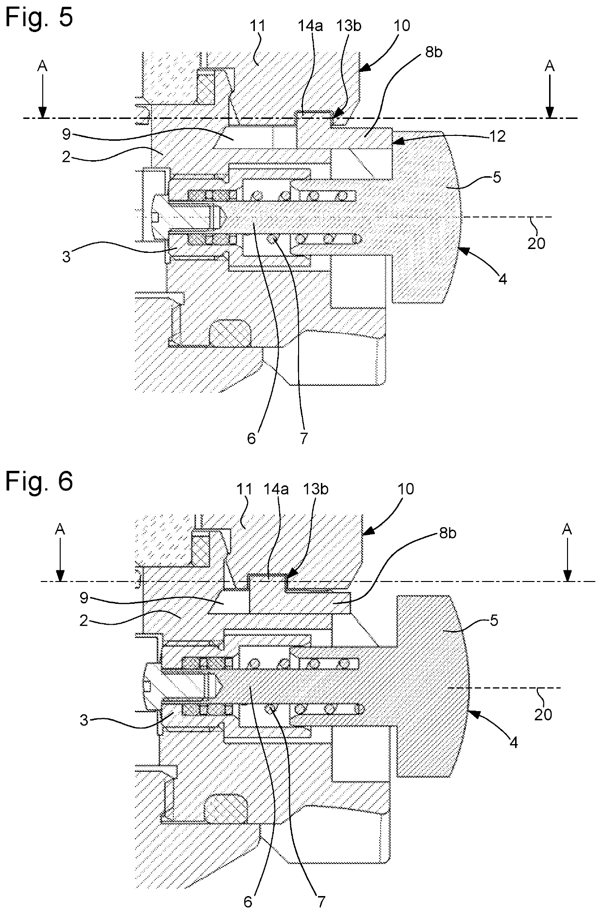
second embodiment

[0036]In a first variant of the second embodiment, the blocking means is a slider 8b adapted to slide in the direction of the actuation axis of the pusher in a radial slide 9 that the case middle contains. The slide 9 may exhibit a dovetail shape or any other suitable profile.

[0037]In a second variant, the control means 10 is formed directly by a rotating bezel 11 that the case contains or supports.

[0038]According to another variant, the cam is formed by a groove 13b housing the pin 14a at least partially and having substantially the width of the diameter of this pin. This configuration corresponds to a desmodromic control, for which the elastic return means of the driving means of the blocking means may be omitted in order to limit the dimensions of the locking device. It may nevertheless be interesting to retain a small elastic return means in this case in order to take up any free play between the component parts and to eliminate any small parasitic translations of the blocking m...


PUM


Abstract

A timepiece is equipped with a case that includes a case middle, a pusher, and a locking device for this pusher. The pusher is arranged movably in a translational manner in an actuation axis. The locking device contains a blocker that is movable in a translational manner along the actuation axis and with the ability to be displaced between a locking position and an unlocking position, in which positions the pusher is respectively to the locking and unlocking positions blocked and free in translation. The locking device contains in addition a control rotatably mounted in a general plane of the case between a first position and a second position corresponding respectively to the locking and unlocking positions for the blocker, this control containing structure for driving the blocker between its locking and unlocking positions.

Description

[0001]This application claims priority from European Patent Application No. 17172883.5 filed on May 24, 2017; the entire disclosure of which is incorporated herein by referenceTECHNICAL FIELD[0002]The present invention relates to the field of watchmaking. It concerns more specifically a timepiece containing a locking device for a pusher that is capable of actuation by a user of the timepiece, in particular a push-button.PRIOR ART[0003]The production of timepieces containing a locking device which permits a push-button to be rendered inactive is familiar. The purpose of these devices is to prevent the accidental actuation of the push-button or, in the case of diver's watches, to avoid the actuation of the push-button under the effect of the external pressure.[0004]Numerous patent applications describing a suchlike locking device are known. For example, application CH678138 proposes a screwed pusher which may be immobilized by a threaded ring that is coaxial with the pusher. The threa...

Claims


Application Information

Patent Timeline
Patent Type & Authority Patents(United States)
IPC IPC(8): G04B37/00G04B3/04G04B47/06G04B19/18G04B37/10G04F7/08
CPCG04B37/0091G04B3/043G04B3/045G04B47/066G04B37/106G04B19/18G04B3/048G04B37/0008G04F7/0866G04B19/283G04B3/046G04B3/001
Inventor LOETSCHER, PHILIPPEKISSLING, GREGORY
Owner OMEGA SA
Why Eureka
Try Eureka