Hybrid composite welded joint

a hybrid composite and welded joint technology, applied in the field of composite materials, can solve the problems of adhesives being susceptible to degradation in aqueous environments, often technologically challenging joints, and using either co-curing or secondary bonding

Inactive Publication Date: 2011-06-14
THE US SECREATRY OF THE NAVY CHIEF OF NAVAL RES OFFICE OF COUNSEL ATTN CODE OOCIP
View PDF58 Cites 33 Cited by
  • Summary
  • Abstract
  • Description
  • Claims
  • Application Information

AI Technical Summary

Benefits of technology

[0008]In view of the foregoing, it is an object of the present invention to provide a improved methodology for joining a nonmetallic composite (e.g., fiber-reinforced matrix) structure and a metallic non-composite (e.g., monolithic) structure.

Problems solved by technology

These kinds of joints are often technologically challenging.
Bolted-bonded configurations are also seen in marine applications involving the joining of composite components to metallic structures; however, adhesives are susceptible to degradation in aqueous environments.
Moreover, for many marine structures, the sizes and shapes of the structural sub-assemblies prohibit the use of either co-curing or secondary bonding as a joining technique.
Some composites also exhibit low temperature creep that leads to loss of preload in the bolts and accelerates damage, a proclivity that may necessitate regular maintenance of the bolted joints to maintain preload.
Bolted lap joints may be impractical for outer hull applications where hydrodynamics (or aerodynamics) is a consideration, because a simple lap joint entails at least one “step” (where the lapped panels overlap) on the hull structure's surface.
Although bolted flange joints can be used for attachment of hull sections, these are significantly heavier than bolted lap joints.
Nevertheless, as previously noted herein, marine use of adhesive bonding can be problematical due to the tendency of adhesive materials to degrade in aqueous environments.

Method used


Image

  • Hybrid composite welded joint
  • Hybrid composite welded joint
  • Hybrid composite welded joint

Examples


Embodiment Construction

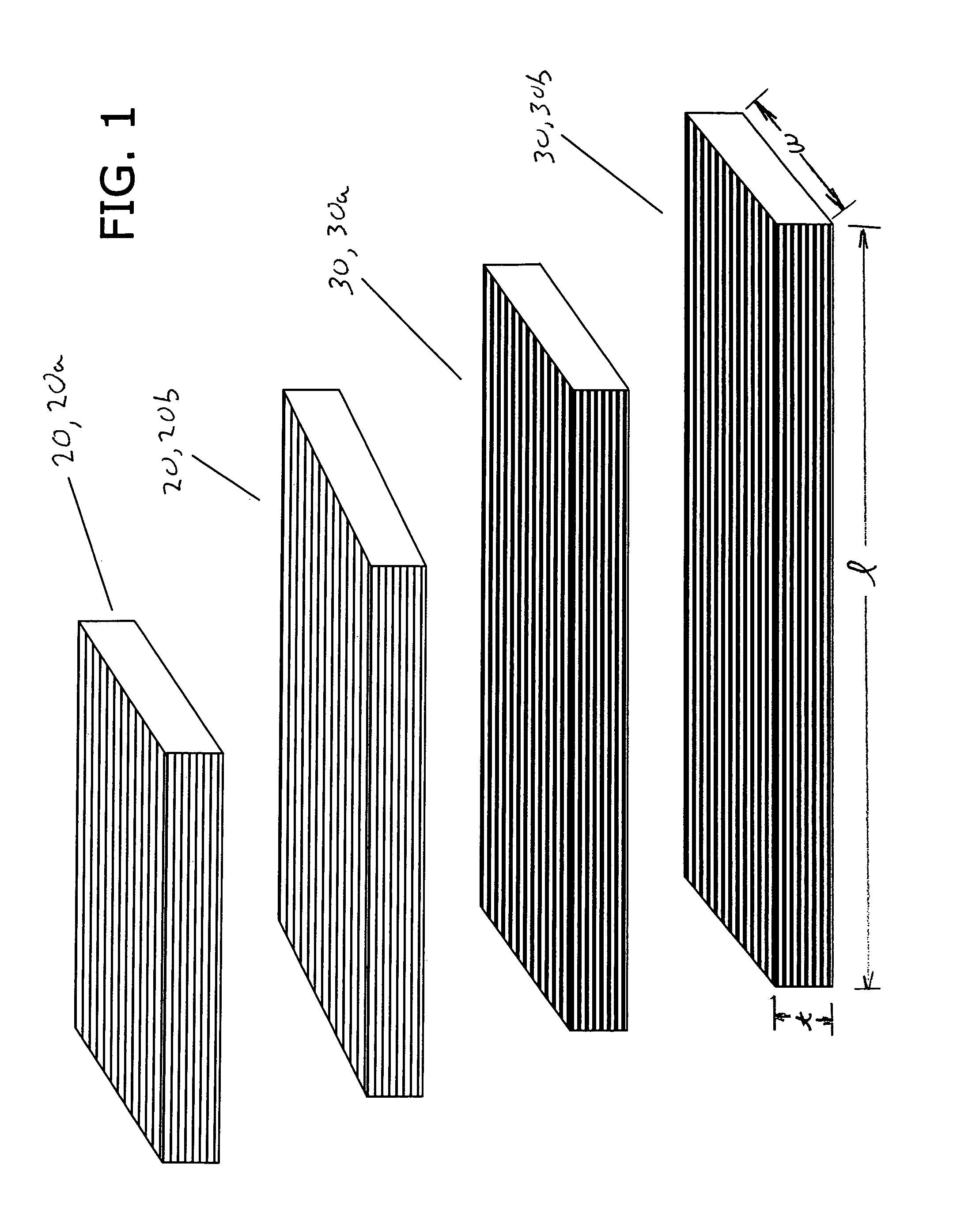
[0033]Reference is now made to FIG. 1, which depicts two nonmetallic fibrous preform panels 20 (viz., 20a and 20b) and two metallic fibrous preform panels 30 (viz., 30a and 30b). The nonmetallic fiber panel preforms 20 are composed, for example, of E-glass woven roving. The metallic fiber panel preforms 30 are composed, for example, of HARDWIRE® unidirectional high strength steel wires. Panels 20 and 30 can be either single-ply or multi-ply. All four panel preforms 20 and 30 are characterized by the same width w and thickness t, but vary in length l.

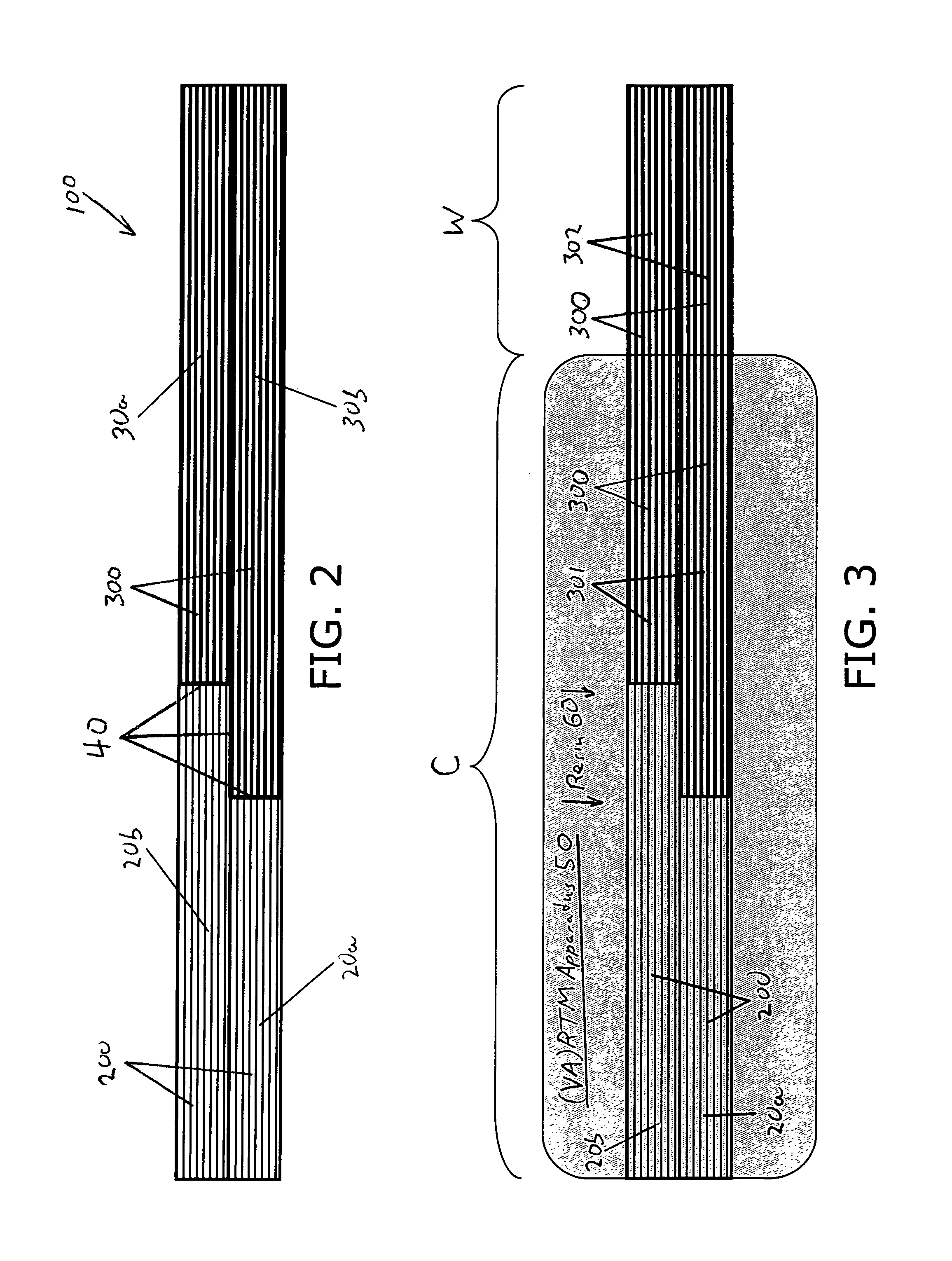
[0034]With reference to FIG. 2, nonmetallic fiber panel performs 20a and 20b are stacked so as to be even at their lefthand edges and to be overlapping at their righthand edges. Similarly, metallic fiber panel preforms 30a and 30b are stacked so as to be even at their righthand edges and to be overlapping at their lefthand edges. The pair of overlapping nonmetallic fiber panel preforms 20a and 20b (at their staggered righthand edges) are...


PUM

PropertyMeasurementUnit
metallicaaaaaaaaaa
structureaaaaaaaaaa
thicknessaaaaaaaaaa

Abstract

The present invention's composite-to-metal attachment methodology—bolt-free and adhesive-free—features the implementation of an intermediary structure containing metallic fibrous material. The intermediary structure couples a first adherend (which contains nonmetallic fibrous material) with a second adherend (which contains metallic nonfibrous material). The intermediary structure's fibrous attribute is availed of for effecting its co-cure attachment to the first adherend. The intermediary structure's metallic attribute is availed of for effecting its weld attachment to the second adherend. According to typical inventive practice, respective panels of the first adherend and the intermediary structure are arranged and connected so as to describe a stepped configuration at the interface between the first adherend and the intermediary structure. The first adherend and a first portion of the intermediary structure are co-impregnated with a uniform resinous system and are co-cured. A second portion of the intermediary structure is welded with respect to the second adherend.

Description

CROSS-REFERENCE TO RELATED APPLICATIONS[0001]This application claims the benefit of U.S. provisional application No. 60 / 643,169, filed 13 Jan. 2005, hereby incorporated herein by reference, entitled “Hybrid Joint,” joint inventors Roger M. Crane, Robert DeNale, Harry E. Prince, and Timothy L. Dapp.STATEMENT OF GOVERNMENT INTEREST[0002]The invention described herein may be manufactured and used by or for the Government of the United States of America for governmental purposes without payment of any royalties thereon or therefor.BACKGROUND OF THE INVENTION[0003]The present invention relates to composites and composite materials, more particularly to methods and configurations for joining composite structures to other composite structures or to non-composite structures.[0004]Many structural applications require the joining of composites to composites, or composites to metals. These kinds of joints are often technologically challenging. Conventional approaches to joining composites with...

Claims


Application Information

Patent Timeline
Patent Type & Authority Patents(United States)
IPC IPC(8): B23K31/02B32B38/08B32B15/14
CPCB23K9/167B23K20/122B23K20/1265B29C70/84B29C70/86B23K2201/18Y10T428/12493B23K2203/18Y10T428/12444B23K2203/16B23K2101/18B23K2103/16B23K2103/172B23K2103/18B29C70/304
Inventor CRANE, ROGER M.DENALE, ROBERTPRINCE, HARRY E.DAPP, TIMOTHY L.TUNIS, III, GEORGE C.
Owner THE US SECREATRY OF THE NAVY CHIEF OF NAVAL RES OFFICE OF COUNSEL ATTN CODE OOCIP
Why Eureka
Try Eureka