Piston position drift control for free-piston device

a free-piston and position drift technology, applied in the direction of machines/engines, engines without rotary main shafts, servomotors, etc., can solve the problems of small drift, severe problems, pressure leakage, etc., and achieve the effect of low susceptibility to damage or fouling, easy adjustment or repair

Inactive Publication Date: 2005-06-07
CLEVER FELLOWS INNOVATION CONSORTIUM INC +1
View PDF10 Cites 4 Cited by
  • Summary
  • Abstract
  • Description
  • Claims
  • Application Information

AI Technical Summary

Benefits of technology

[0009]The invention according to the following aspects provides a piston position drift control that is passive, requires no active control once in service, provides low susceptibility to damage or fouling, and is amenable to adjustment or repair if needed. In addition, the control is small and inexpensive, and functions across the entire operational range of a free-piston device it supports. A related free-piston device including the piston position drift control is also provided.

Problems solved by technology

In practice, these pressure leakages arise due to geometric anomalies or asymmetric pressure-position relationships.
As a result, drift occurs minimally at low strokes, but becomes a severe problem at higher strokes.
In this case, the undesired pressure difference drives a corrective gas flow.
However, centerports are not ideal for all situations.
For instance, they do not work well if there is a significant phase angle between pressure and motion, i.e. when a substantial pressure difference exists at the times when there is port alignment (in a centered piston position).
In this case, the otherwise corrective flow of the centerport leads to a wasteful flow loss at the ports.
Unfortunately, a large class of commercially significant machines exhibit such a phase shift, making centerport systems too inefficient for use with these machines.
Centerports also create at least some minimum, unavoidable loss for low-phase devices (e.g., free-piston Stirling engines) since there is always some phase difference.
These small orifices are susceptible to clogging, as well as being costly to manufacture.
Centerports are also completely contained within the deepest parts of the free-piston device, which requires costly disassembly and / or part replacement if a malfunction occurs.
Further, even without a discrete malfunction, there is no mechanism for adjusting centerports while in service to compensate for changing conditions in the seal or drift.
Such systems work well, but require extensive external, pressurized piping and valves, as well as costly position sensors and a controller.
However, the external plumbing is more susceptible to leakage and damage, and the increased complexity implies lower reliability.
However, the acoustic bypass is sensitive to operating frequency.
In addition, an acoustic bypass is difficult to apply efficiently due to actual gas flow losses near the ends of the tube unless the drift to be corrected is very slight.

Method used


Image

  • Piston position drift control for free-piston device
  • Piston position drift control for free-piston device
  • Piston position drift control for free-piston device

Examples


Embodiment Construction

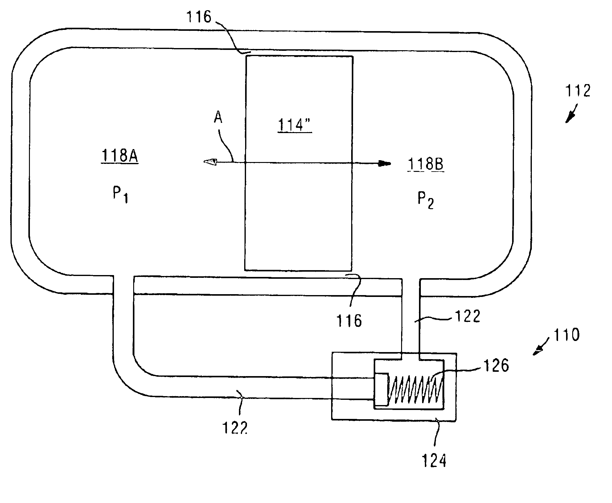
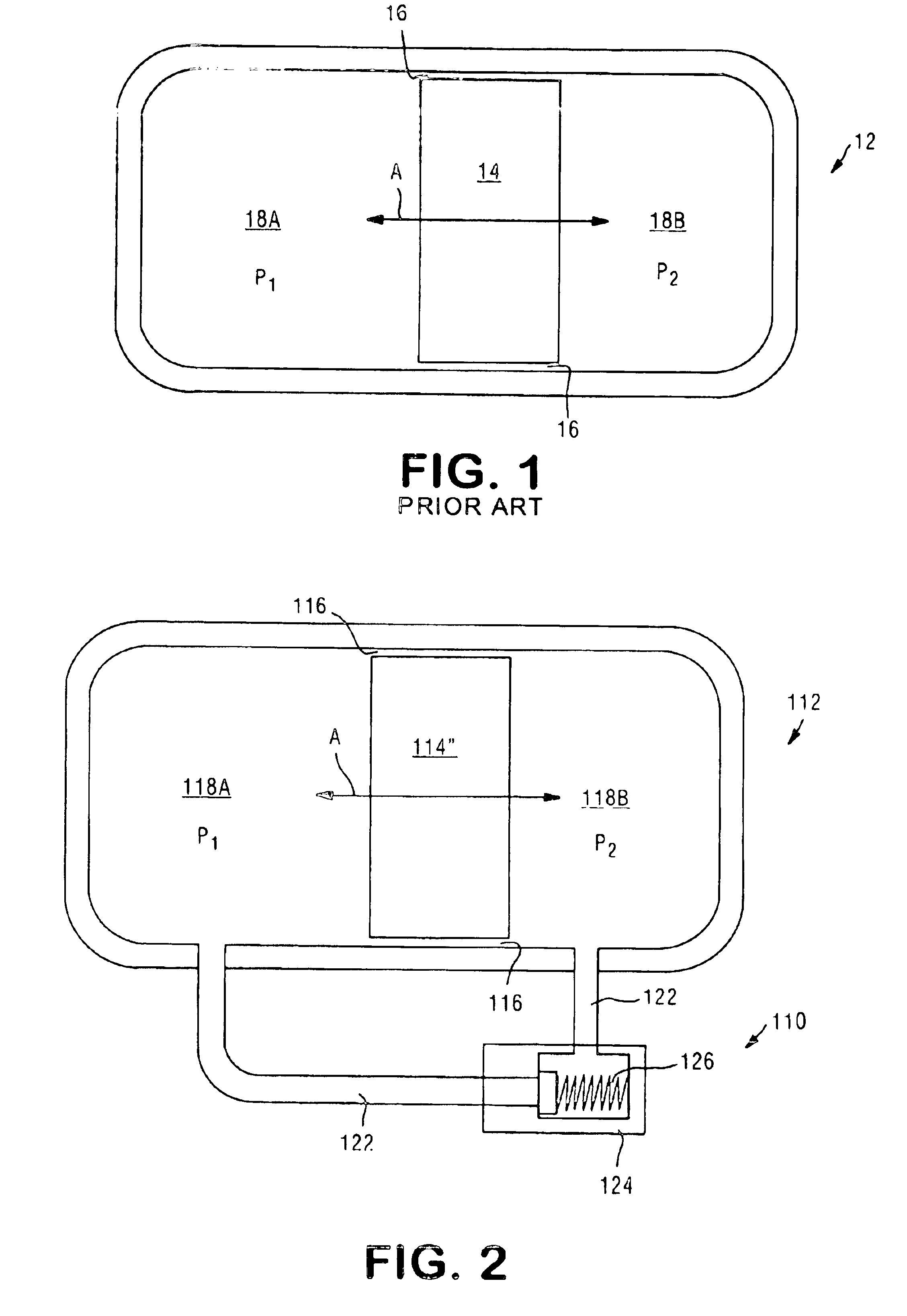
[0020]Referring to FIG. 1, a conventional free-piston device 12 includes a reciprocating piston 14 with a seal 16 between internal volumes 18A and 18B adjacent to piston 14. The reciprocating motion of piston 14 is indicated by arrow A. In free-piston devices 12, a pressure wave is created (by structure not shown) in at least one internal volume 18A, 18B. Such pressure waves give rise to time-variant pressure differences (i.e., times when P1 does not equal P2) across seal 16 that drive leakage flows alternating back and forth across seal 16. Typically, such pressure differences are cyclic and reversing. Under certain conditions, a net leakage flow in one direction across seal 16 can occur. Factors that contribute to these conditions may include, for example, overall operating conditions, seal geometries, and phase relationships between the pressure wave and the motion. A leakage flow that tends to accumulate fluid on one side of piston 14 pushes the average position of piston 14 awa...


PUM


Abstract

A piston position drift control for a free-piston device. The control includes a passage connecting internal volumes of the device, the passage being substantially shorter than an acoustic wavelength of the device; and a check valve in the passage for controlling fluid communication between the internal volumes, the check valve having an opening pressure not less than approximately 20% of a maximum pressure differential of the device at a maximum stroke. The control is passive, requires no active control once in service, provides low susceptibility to damage or fouling, and is amenable to adjustment or repair if needed. In addition, the control is small and inexpensive, and functions across the entire operational range of a free-piston device it supports. A related free-piston device including the piston position drift control is also provided.

Description

CROSS REFERENCE TO RELATED APPLICATIONS[0001]This application claims the benefit of provisional application Ser. No. 60 / 368,948, filed Mar. 29, 2002.TECHNICAL FIELD[0002]The present invention relates generally to piston position drift control for a free-piston device, and more particularly, to a passive piston position drift control using a check valve and a related free-piston deviceBACKGROUND ART[0003]Direct conversion of alternating current (AC) electric power into reciprocating mechanical power by resonant motors, and the reverse conversion in alternators, has become important in applications like pulse-tube and Stirling-cycle cryocoolers and small externally-heated engine-generators operating on a thermoacoustic or Stirling cycle. Unlike more common rotary motors, the moving parts in such devices reciprocate, typically along the central axis of the assembly. The movement is typically guided with non-contacting bearings or non-rubbing flexures, enabling use of non-contacting and...

Claims


Application Information

Patent Timeline
Patent Type & Authority Patents(United States)
IPC IPC(8): F01B11/00F02B77/08
CPCF01B11/00F02B77/08F02G2243/54F15B11/08
Inventor COREY, JOHN A.SPOOR, PHILIP S.
Owner CLEVER FELLOWS INNOVATION CONSORTIUM INC
Why Eureka
Try Eureka