Contaminant reducing device

a technology of reducing device and reducing device, which is applied in the direction of machines/engines, electrochemical generators, separation processes, etc., can solve the problems of air pollution, harmful substances in the exhaust gas generated in the fuel combustion process, etc., and achieve the effect of reducing system installation and maintenance costs, increasing the utilization of space in the ship, and improving system efficiency

Active Publication Date: 2020-09-29
SAMSUNG HEAVY IND CO LTD
View PDF48 Cites 0 Cited by
  • Summary
  • Abstract
  • Description
  • Claims
  • Application Information

AI Technical Summary

Benefits of technology

[0015]According to embodiments of a contaminant reducing device of the inventive concept, nitrogen monoxide contained in exhaust gas is oxidized with an oxidizing agent generated in a purification unit for electrolyzing seawater, and, at the same time, acidified cleaning water is neutralized with a neutralizing agent generated in the same purification unit. This cannot only reduce the system installation and maintenance cost but also can increase the utilization of space in a ship.
[0016]In addition, hydrogen generated by the electrolysis of seawater in the purification unit is supplied to a fuel cell module to generate electricity, and the generated electricity is used as a driving source of the purification unit and other devices. Therefore, the system can be operated more efficiently.
[0017]Further, according to embodiments of the contaminant reducing device of the inventive concept, since fine dust is removed before sulfur oxides and nitrogen oxides are oxidized, the oxidation efficiency can be improved. In addition, since the oxidized exhaust gas is double purified as it passes through a wet scrubber, contaminants contained in the exhaust gas can be significantly reduced. Also, the oxidized exhaust gas is dissolved in cleaning water to produce strong acid that can kill microorganisms in the cleaning water.
[0018]Moreover, according to embodiments of the contaminant reducing device of the inventive concept, the reduction of oxidized sulfur oxides and nitrogen oxides can be prevented by injecting a liquid catalyst into the oxidized sulfur oxides and nitrogen oxides before a gas-liquid contact. Therefore, the reduction effect of the sulfur oxides and the nitrogen oxides can be improved. In addition, since the oxidized exhaust gas is double purified as it passes through the wet scrubber, contaminants in the exhaust gas can be significantly reduced.

Problems solved by technology

Here, exhaust gas generated in the fuel combustion process contains harmful substances such as sulfur oxides (SOx), nitrogen oxides (NOx), and fine dust (PM).
Thus, if the exhaust gas is discharged as it is, it can cause air pollution.

Method used


Image

  • Contaminant reducing device
  • Contaminant reducing device
  • Contaminant reducing device

Examples


first embodiment

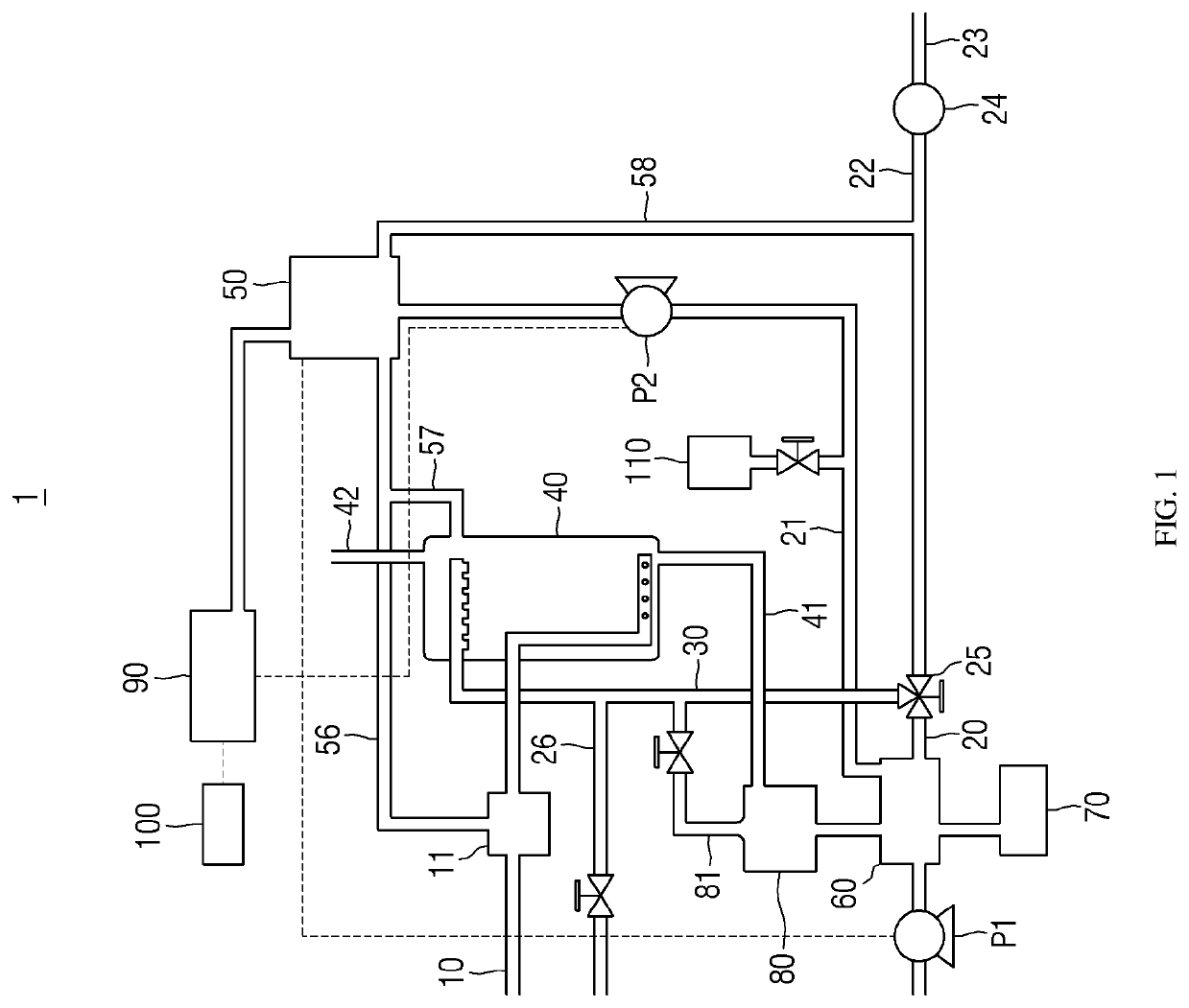
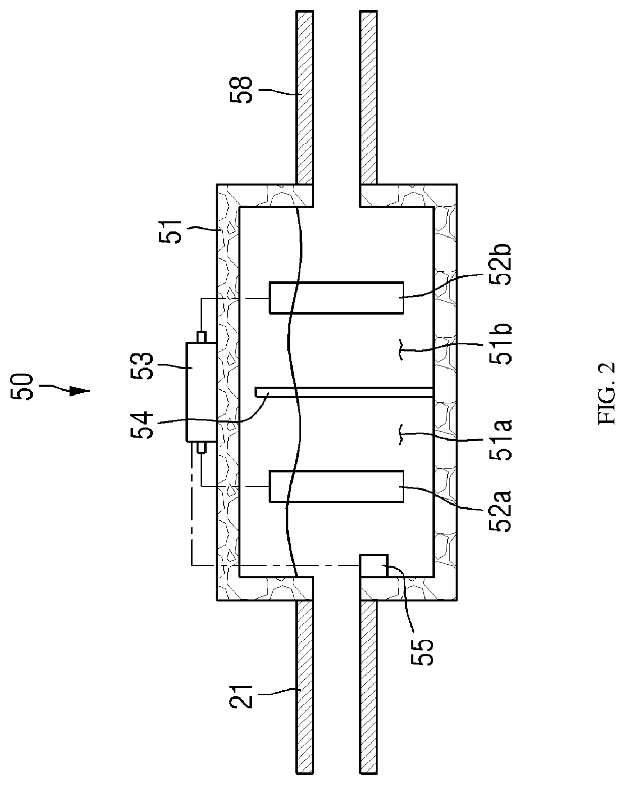
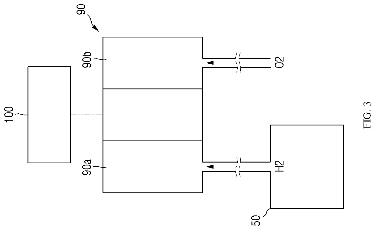
[0033]Hereinafter, a contaminant reducing device according to the inventive concept will be described in detail with reference to FIGS. 1 through 5.

[0034]A contaminant reducing device according to an embodiment of the inventive concept a device capable of reducing the concentration of various contaminants (nitrogen oxides, sulfur oxides, dust, etc.) contained exhaust gas to discharge that meets exhaust standards while treating cleaning water used to reduce the concentration of exhaust gas. The contaminant reducing device is mainly mounted on a ship to remove contaminants of exhaust gas generated in the ship.

[0035]The contaminant reducing device oxidizes nitrogen monoxide contained in exhaust gas with an oxidizing agent generated in a purification unit for electrolyzing seawater and, at the same time, neutralizes acidified cleaning water with a neutralizing agent generated in the same purification unit, thereby reducing the system installation and maintenance cost and increasing the ...

second embodiment

[0083]Hereinafter, a contaminant reducing device according to the inventive concept will be described in detail with reference to FIGS. 6 through 11.

[0084]The contaminant reducing device can improve oxidation efficiency by removing fine dust before oxidizing sulfur oxides and nitrogen oxides. In addition, since oxidized exhaust gas is double purified as it passes through a wet scrubber, contaminants in the exhaust gas can be significantly reduced. Also, the oxidized exhaust gas is dissolved in cleaning water to produce strong acid that can kill microorganisms in the cleaning water.

[0085]The contaminant reducing device will now be described in detail with reference to FIGS. 6 and 7.

[0086]FIG. 6 is a schematic view of a contaminant reducing device according to a second embodiment of the inventive concept. FIG. 7 is a cross-sectional view of an example of a pretreatment unit of FIG. 6.

[0087]The contaminant reducing device 200 according to the inventive concept includes an exhaust gas t...

third embodiment

[0130]Hereinafter, a contaminant reducing device according to the inventive concept will be described in detail with reference to FIGS. 12 through 14.

[0131]The contaminant reducing device according to the third embodiment of the inventive concept can prevent the reduction of oxidized sulfur oxides and nitrogen oxides by injecting a liquid catalyst into the oxidized sulfur oxides and nitrogen oxides before a gas-liquid contact. Therefore, the reduction effect of the sulfur oxides and the nitrogen oxides can be improved. In addition, since the oxidized exhaust gas is double purified as it passes through a wet scrubber, contaminants in the exhaust gas can be significantly reduced.

[0132]FIG. 12 is a schematic view of a contaminant reducing device according to a third embodiment of the inventive concept.

[0133]The contaminant reducing device 400 according to the inventive concept includes an exhaust gas tube 410, a cleaning water supply tube 420, a scrubber 430, an oxidation unit 440, a l...


PUM

PropertyMeasurementUnit
temperatureaaaaaaaaaa
weight ratioaaaaaaaaaa

Abstract

A contaminant reducing device is provided. The contaminant reducing device comprises: an exhaust gas tube for supplying exhaust gas from a combustion engine; a cleaning water supply tube for supplying cleaning water; a scrubber for spraying cleaning water, which is supplied through the cleaning water supply tube, to exhaust gas supplied through the exhaust gas tube; an oxidation unit connected to the exhaust gas tube so as to oxidize the exhaust gas by discharging electricity, emitting ultraviolent rays, or spraying an oxidizer; and a cleaning water discharge tube for discharging cleaning water from inside the scrubber.

Description

RELATED APPLICATION INFORMATION[0001]This patent claims priority from International PCT Patent Application No. PCT / KR2016 / 003156, filed Mar. 28, 2016 entitled, “CONTAMINANT REDUCING DEVICE”, which claims priority to Korean Patent Application Nos. 10-2015-0128596, filed Sep. 10, 2015, 10-2015-0131169, filed Sep. 16, 2015 and 10-2016-0001669, filed Jan. 6, 2016, all of which are incorporated herein by reference in their entirety.[0002]NOTICE OF COPYRIGHTS AND TRADE DRESS[0003]A portion of the disclosure of this patent document contains material which is subject to copyright protection. This patent document may show and / or describe matter which is or may become trade dress of the owner. The copyright and trade dress owner has no objection to the facsimile reproduction by anyone of the patent disclosure as it appears in the Patent and Trademark Office patent files or records, but otherwise reserves all copyright and trade dress rights whatsoever.BACKGROUND[0004]The present inventive con...

Claims


Application Information

Patent Timeline
Patent Type & Authority Patents(United States)
IPC IPC(8): A61L9/20H01M8/0656F01N3/28B01D47/06B01D53/78F01N3/08F01N3/04F01N3/037H01M8/1018
CPCF01N3/04A61L9/20B01D47/06F01N3/2896B01D53/78F01N3/0821F01N3/0892H01M8/0656F01N3/037H01M2008/1095F01N2590/02F01N2240/28F01N2240/05B01D2257/404B01D2259/4566F01N2240/32Y02A50/20B01D2251/108B01D2221/08B01D2251/10F01N2610/01B01D2247/04B01D2252/1035B01D2257/302Y02E60/50
Inventor LEE, SEUNG JAEPARK, HEE JUNPARK, GUN IL
Owner SAMSUNG HEAVY IND CO LTD
Why Eureka
Try Eureka