Device and method for cleaning a wellbore equipment

a technology for cleaning equipment and wellbore equipment, which is applied in the direction of cleaning apparatus, earthwork drilling and mining, and wellbore/well accessories. it can solve the problems of affecting the recovery of formation fluid. , to achieve the effect of improving the recovery of formation fluid

Active Publication Date: 2020-12-15
BLUE SPARK ENERGY
View PDF19 Cites 1 Cited by
  • Summary
  • Abstract
  • Description
  • Claims
  • Application Information

AI Technical Summary

Benefits of technology

[0011]The device according to the invention allows therefore generating shock waves in a transmitting fluid, such as e.g. water or oil, retained by the retaining module so that it is transmitted up to the equipment to be cleaned. In the present description, the terms “wellbore liquid level” means the level of the liquid (or mix of liquids) that fills at least partially the wellbore and the terms “retained liquid” means the liquid that is retained by the retaining module of the device according to the invention. The device according to the invention allows thus efficiently, easily and rapidly to remove deposits from a wellbore equipment arranged in a wellbore, wherever the location of said wellbore in regard to the wellbore liquid. The wellbore equipment may be a completion string equipment, a tubing, a casing, etc. Thus, for example, the method may be advantageously used to remove deposits from a metallic casing disposed in the wellbore, improving therefore the recovery of formation fluids and / or gases. The device according to the invention provides an electrohydraulic cleaning process for efficiently and rapidly removing deposits from a wellbore equipment. In other words, electrohydraulic energy allows cleaning a wellbore equipment in order to improve the recovery of oil and / or gas. The device is a source of electrohydraulic energy, which allows advantageously removing deposits and cleaning equipment arranged in a wellbore whatever their location in said wellbore.
[0031]Preferably, the membrane is deformable and / or flexible and / or elastic in order to prevent the at least one shock wave to bounce on it and to conduct efficiently the at least one shock wave toward the wellbore equipment.

Problems solved by technology

In any event, after a period of production, injection or transportation of fluids or gases, there is a tendency for the different wellbore equipment to become plugged with various types of deposits such as debris or residues.
For example, organic residues like scale, paraffin, asphalts and other gummy residues of petroleum origin often cause plugging problems.
Usually these deposits can cause significant problems, because of their composition and the fact that they can precipitate under certain conditions (pressure, temperature, composition).
Such deposits are difficult to dissolve by known chemical means or to dislodge by known mechanical means.
However, such techniques, while less expensive than a complete workover, are substantially less effective, since they are incapable, in most cases, of dissolving significant amounts of the plugging materials.
However, brushes, scrapers or pigs are quite inefficient removing encrusted deposits in areas of the wellbore equipment accessible with difficulty or inaccessible.
Consequently, it is often necessary to rework the well and replace one or several equipment of the completion string or the pipeline.
Such tactics are, of course, both time-consuming and expensive.
Consequently, it is only possible to efficiently remove deposits on parts of wellbore equipment that are arranged under the surface of the liquid, i.e. that are immersed in the liquid.
Such solution may be significantly time-consuming and costly.

Method used


Image

  • Device and method for cleaning a wellbore equipment
  • Device and method for cleaning a wellbore equipment
  • Device and method for cleaning a wellbore equipment

Examples


Embodiment Construction

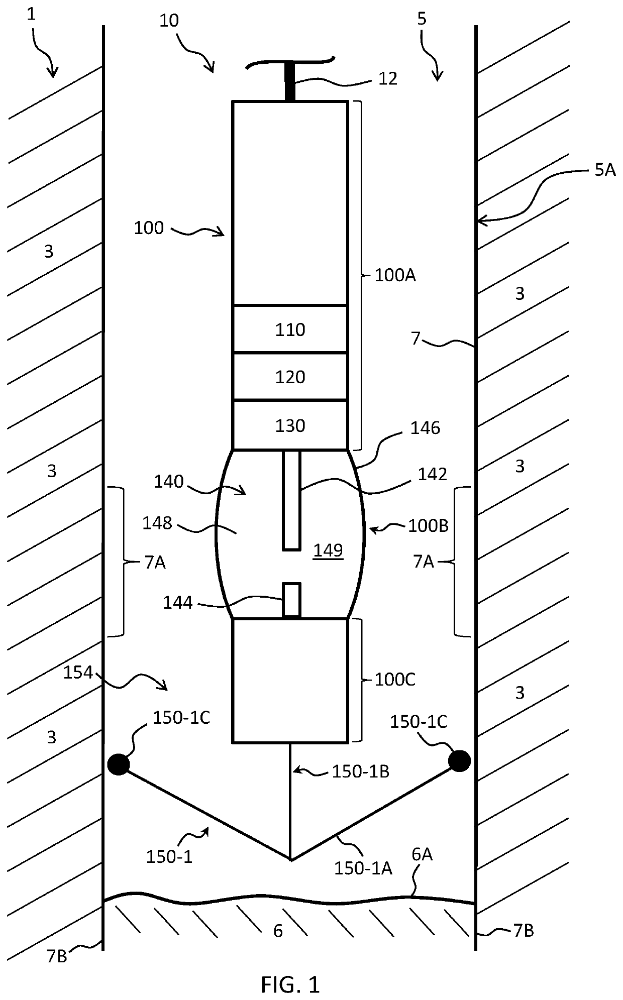
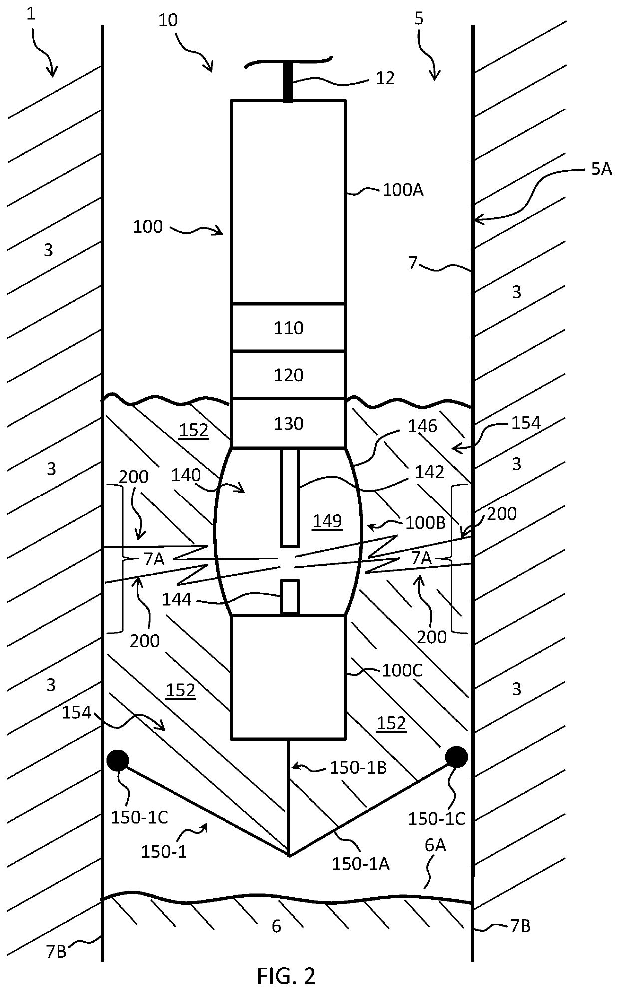
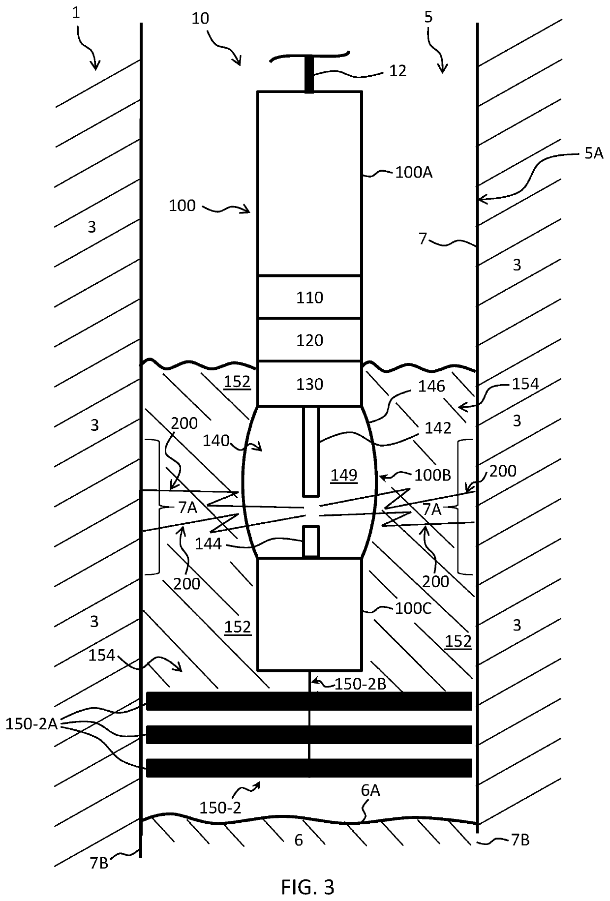
[0048]The Specification, which includes the Summary of Invention, Brief Description of the Drawings and the Detailed Description of the Preferred Embodiments, and the appended Claims refer to particular features (including process or method steps) of the invention. Those of skill in the art understand that the invention includes all possible combinations and uses of particular features described in the Specification. Those of skill in the art understand that the invention is not limited to or by the description of embodiments given in the Specification. The inventive subject matter is not restricted except only in the spirit of the Specification and appended Claims. Those of skill in the art also understand that the terminology used for describing particular embodiments does not limit the scope or breadth of the invention. In interpreting the Specification and appended Claims, all terms should be interpreted in the broadest possible manner consistent with the context of each term. A...


PUM


Abstract

The invention relates to an electrical discharge generating device for cleaning an equipment arranged in a wellbore of a subterranean formation in order to improve the recovery of formation fluids and / or gases, said electrical discharge generating device comprising a discharge unit for generating at least one electrical discharge that propagates at least one shock wave for cleaning from said equipment, wherein said electrical discharge generating device further comprises a retaining module configured for retaining a volume of liquid in order to immerse the discharge unit.

Description

FIELD OF THE INVENTION[0001]The field of the invention relates to the treatment of a wellbore equipment and, more particularly, to a device and a method for removing deposits from an equipment arranged in a wellbore of a subterranean formation in order to improve the recovery of formation fluids and / or gases. The device and method according to the invention may advantageously be used to remove deposits from e.g. a casing, a tubing or a well completion equipment.BACKGROUND OF THE INVENTION[0002]In the art of well boring, a borehole is drilled into the earth through the oil or gas producing subterranean formation or, for some purposes, through a water bearing formation or a formation into which water or gas or other liquids are to be injected.[0003]Completion of a well may be carried out in a number of ways dependent upon the nature of the formation of interest. In particular, it is known to arrange a casing into the wellbore to control formation elements. Once installed into the well...

Claims


Application Information

Patent Timeline
Patent Type & Authority Patents(United States)
IPC IPC(8): E21B37/00E21B37/10
CPCE21B37/10E21B37/00
Inventor FENSKY, CHARLESHARRIES, ROBERTPETTEN, STEVE
Owner BLUE SPARK ENERGY
Why Eureka
Try Eureka