Tire

a technology of tires and treads, applied in the field of tires, can solve the problems of affecting the traction performance the deterioration of the steering stability performance on a dry road surface, and the inability to extend the opening so as to achieve a larger snow column shearing force, improve the traction performance, and improve the traction effect of the first sip

a technology of tires and treads, applied in the field of tires, can solve the problems of affecting the traction performance the deterioration of the steering stability performance on a dry road surface, and the inability to extend the opening so as to achieve a larger snow column shearing force, improve the traction performance, and improve the traction effect of the first sip

US11007823B2Active Publication Date: 2021-05-18SUMITOMO RUBBER IND LTD

Image

  • Tire
  • Tire
  • Tire

Examples


Embodiment Construction

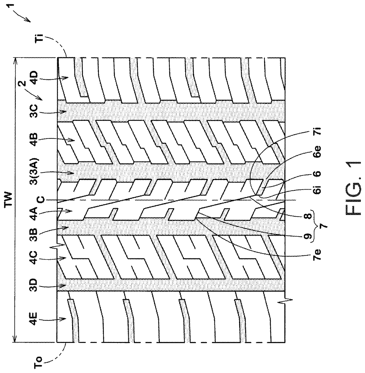
[0022]Hereinafter, one embodiment of the invention will be described on the basis of the drawings. FIG. 1 is a planar figure of a tread portion 2 of a tire 1 illustrating one embodiment of the invention. In the present embodiment, as a preferred aspect, an all season tire for a four-wheel drive vehicle is illustrated. The disclosure can be applied not only to pneumatic tires for passenger cars or heavy loads, but also to non-pneumatic tires.

[0023]The tire 1 of the present embodiment includes an asymmetric tread portion 2 in which a direction of attachment to a vehicle is defined. The tread portion 2 includes an inner tread end Ti positioned on a vehicle inner side when being attached to the vehicle and an outer tread end To positioned on a vehicle outer side when being attached to the vehicle.

[0024]The inner tread end Ti and the outer tread end To are respectively defined as ground contact positions on both of the outermost sides in a tire axial direction when a normal state tire on...


PUM


Abstract

Provided is a tire in which a first land portion partitions a first main groove from a second main groove. A first lug groove and a first sipe are provided in the first land portion. One end of the first lug groove communicates with the first main groove. The first sipe includes one end communicating with the second main groove and another end communicating with another end of the first lug groove. The first sipe includes a steeply inclined portion extending from the another end of the first lug groove and having an angle with respect to a tire circumferential direction smaller than that of the first lug groove, and a gently inclined portion extending from the steeply inclined portion to the second main groove and having an angle with respect to the tire circumferential direction larger than that of the steeply inclined portion.

Description

CROSS-REFERENCE TO RELATED APPLICATION[0001]This application claims the priority of Japan patent application serial no. 2017-152202, filed on Aug. 7, 2017. The entirety of the above-mentioned patent application is hereby incorporated by reference herein and made a part of this specification.BACKGROUNDTechnical Field[0002]The disclosure relates to a tire and, specifically, to a tire suitable for traveling on a snowy road.Description of Related Art[0003]For example, tires intended for traveling on a snowy road have been proposed. In a tread portion of this type of tire, for example, lug grooves extending in a tire axial direction are formed. The lug grooves enhance traveling performance on a snowy road (hereinafter sometimes simply referred to as “snowy road performance”) by causing the snow to be pressed down and sheared.[0004]In order to further enhance the snowy road performance, for example, it is conceivable to increase a groove volume in each of the lug grooves. However, with su...

Claims


Application Information

Patent Timeline
18 May 2021
Publication
US11007823B2
IPC
B60C11/12; B60C11/03; B60C11/13
CPC
B60C11/1204; B60C11/0304; B60C11/0306; B60C2011/0341; B60C2011/0346; B60C2011/0372; B60C2011/0381; B60C2011/0383
Inventors
ARAI, HIROSHI