Print head for printing a suspension fluid comprising particles, printing apparatus and method

a printing head and suspension fluid technology, applied in food shaping, food science, food coating and other directions, can solve the problems of clogging of the nozzle, affecting the printing effect, and affecting the printing effect, and achieve the effect of stable droplet flow and printing

Inactive Publication Date: 2018-12-25
NEDERLANDSE ORG VOOR TOEGEPAST NATUURWETENSCHAPPELIJK ONDERZOEK TNO
View PDF4 Cites 0 Cited by
  • Summary
  • Abstract
  • Description
  • Claims
  • Application Information

AI Technical Summary

Benefits of technology

[0006]It is an object of the present invention to provide a method and device for printing suspension fluids, wherein the abovementioned disadvantages have been overcome, which is reliable and provides for a stable droplet flow useable for printing.
[0010]The distinguishing features of the present invention resolve the above problems by increasing the shear within the flow at least prior to the nozzle outlet. By increasing the shear, pulling forces within the flow acting on the agglomerations will cause the agglomerations to break, thereby separating the particles. The absence of agglomerations effectively prevents bridge formation. However, to increase the shear rate sufficiently in the supply to the nozzle, the dimensions of the flow path before the nozzle must locally become so small that the problem of clogging shifts to the location of the reduced channel size. As a result, increasing the shear rate without taking any other measures merely moves the problem of bridge formation to the flow path before the nozzle outlet. Therefore, in accordance with the present invention, in addition to increasing the shear rate, a return flow path has been provided for removing excess fluid away from the nozzle. As a result of the return path, the flow rate in the supply channel of the flow path can be larger than the flow rate through the one or more nozzle outlets. This larger flow rate allows to obtain larger shear forces in the flow before the nozzle outlet, while simultaneously allowing the flow path to have larger dimensions than the nozzle outlet. The clogging of the nozzle is thereby resolved.
[0014]Moreover, in accordance with yet a further embodiment, at least one of the one or more nozzle outlets is located in a wall of the supply channel, and wherein the supply channel is connected to the return channel. The advantage of providing the nozzle outlet directly in the flow path in the wall of the supply channel, is that the flow from the supply channel to the return path flows past the outlet. As a result, shear force of the flow passing over the outlet further prevent any pollution or particles from blocking the opening. A slight disadvantage is that this also causes the droplet stream from the nozzle outlet to have a velocity component in the direction of the original flow which in most cases must be compensated. Therefore, in accordance with some embodiments, at least one of the one or more nozzle outlets is located in a wall of a branch channel extending from the supply channel. In such a branch channel, e.g. extending transverse to the supply channel, a shear force of a flow passing over the nozzle outlet will be absent. The branch channel may for example be closed on one end.
[0015]In order for the pressure fluctuations imparted by the actuator on the outlet to effectively transfer the fluctuations on the ejected fluid, some room around each one of the one or more nozzle outlets is also desired. The pressure fluctuations are to be advantageously imparted on the ejected fluid with minimum pressure loss (e.g. due to back flow of suspension fluid under influence of the pressure pulses). To this end, the actuator may comprise a suitably shaped focusing member at a suitable distance from the outlet channel. Therefore, in accordance with yet another embodiment, at least one of the one or more nozzle outlets is located in a nozzle chamber which is connected to the supply channel for receiving the suspension fluid, the nozzle chamber comprising the actuator for imparting the pressure fluctuations. The nozzle chamber allows to be suitably shaped and dimensioned in the design. According to some embodiments, the nozzle chamber is connected to the supply channel via a branch channel extending from the supply channel, the nozzle chamber being sized or shaped for imparting said pressure fluctuations. Arranging the nozzle chamber in a branch extending from the supply channel again has the advantage of preventing the ejected droplet stream to have a velocity component in an undesired direction.
[0016]In some of the embodiments of the print head described herein above, the branch channel comprising the nozzle outlet, or connecting the nozzle chamber to the supply channel, extends from an inner bend of a bended portion of the supply channel. As a result of this, larger particles or particle agglomerations that inadvertently have not been broken-up by the shear force in the shear section will mostly be conveyed in the flow near the outer bend as a result of centrifugal forces. The flow near the inner bend of the bended portion will therefore mostly carry the smaller separated particles. This will further decrease the chance on clogging of the nozzle outlets.
[0018]In accordance with another embodiment of the present invention, the print head further comprises a return pump cooperating with the supply pump for controlling a volumetric flow rate ejected from the one or more nozzle outlets. By setting the supply pump at a first volumetric flow rate, while setting the return pump at a second volumetric flow rate (smaller than the first volumetric flow rate), the difference will be the volumetric flow rate that must have been forced through the nozzle outlets that are located in between the supply pump and the return pump. This, thereby, allows to control the amount of suspension fluid printed. In an embodiment having multiple nozzle outlets, if one of the outlets for some reason would become clogged anyway (despite the measures taken), the flow rate through the other nozzles can be controlled in this manner.

Problems solved by technology

As a result of the bridge formation, the nozzle will become clogged.
This problem is likely to occur with suspension fluids comprising large particles, and may therefore expectedly be diminished by making the outlet opening of the nozzle larger.
However, this would likewise increase the flow through the nozzle outlet, resulting in larger droplets (which is in many cases not desired).
Moreover, enlarging the nozzle outlet is also not sufficiently effective to resolve the problem.
It has been found that suspension fluids with small particles may likewise clog the nozzle, and bridge formation alone does not explain this.
Therefore, even with small particles, clogging may occur.

Method used


Image

  • Print head for printing a suspension fluid comprising particles, printing apparatus and method
  • Print head for printing a suspension fluid comprising particles, printing apparatus and method
  • Print head for printing a suspension fluid comprising particles, printing apparatus and method

Examples


Embodiment Construction

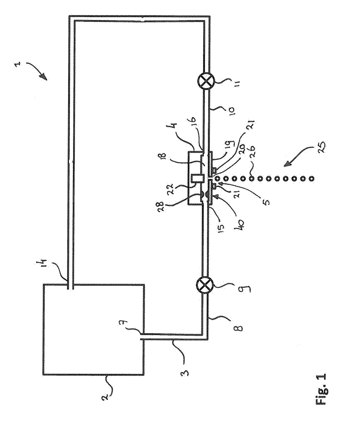
[0035]A schematic illustration of the principles of a printing system or printing apparatus in accordance with the present invention is provided in FIG. 1. The printing apparatus 1 comprises a suspension fluid container 2. The suspension fluid container 2 comprises a suspension fluid which is to be printed using a print head 4 in accordance with the present invention. The suspension fluid may for example comprise a liquid including a suspension of particles. For example, the suspension fluid may be water including a suspension of a food ingredient in the form of particles. Instead of water, a different liquid having a different viscosity and different properties may be applied. For example, the liquid could be an oil having a suspension of the food ingredient. Instead of a food ingredient, the printing apparatus of the present invention may also be used for printing other suspensions, such as a liquid comprising a pharmaceutical component (e.g. a medicine in the form of a powder) or...


PUM

PropertyMeasurementUnit
heightaaaaaaaaaa
heightaaaaaaaaaa
heightaaaaaaaaaa

Abstract

The invention is directed at a print head for printing a suspension fluid. The print head comprises a nozzle having one or more nozzle outlets for allowing the suspension fluid to be ejected from the nozzle, a flow path including a supply channel for supplying the suspension fluid to the one or more nozzle outlets, and a supply pump for establishing a flow within the flow path. The nozzle further comprises an actuator for imparting pressure fluctuations on the suspension fluid at the one or more nozzle outlets for generating a stream of droplets therefrom. The flow path further comprises a shear section for locally increasing the shear rate at least at a location in the flow path upstream of the one or more nozzle outlets. The flow path further includes a return channel for allowing excess fluid not ejected from the nozzle to flow away from the one or more nozzle outlets. The shear section is configured to locally increase the shear rate to be larger than a shear rate obtained near at least one of the one or more nozzle outlets. The invention is further directed at a printing apparatus, a method of printing, and a method of manufacturing a print head.

Description

[0001]This application is the U.S. National Phase of, and Applicants claim priority from, International Patent Application Number PCT / NL2015 / 050753 filed 29 Oct. 2015, which claims priority from EP 14190858.2 filed 29 Oct. 2014, each of which is incorporated herein by reference.FIELD OF THE INVENTION[0002]The present invention is directed at a print head for printing a suspension fluid, the print head comprising a nozzle having one or more nozzle outlets for allowing the suspension fluid to be ejected from the nozzle, a flow path including a supply channel for supplying the suspension fluid to the one or more nozzle outlets, and a supply pump for establishing a flow within the flow path. The invention is further directed at a printing apparatus comprising such a print head, to a method of printing suspension fluids, and to a method of manufacturing a print head.BACKGROUND[0003]A recent development in the field of three dimensional printing technology is the application 3D printing t...

Claims


Application Information

Patent Timeline
Patent Type & Authority Patents(United States)
IPC IPC(8): B41J2/14B29C64/112A23P30/20A23P20/25
CPCB41J2/14B29C64/112A23V2002/00A23P2020/253A23P30/20B41J2202/11B41J2202/12
Inventor RIJFERS, ANDRIESHOUBEN, RENE JOSKOLDEWEIJ, ROBIN BERNARDUS JOHANNES
Owner NEDERLANDSE ORG VOOR TOEGEPAST NATUURWETENSCHAPPELIJK ONDERZOEK TNO
Why Eureka
Try Eureka