Dryer with a heat pump and an electrical heating element and also a method for its operation

a technology of electrical heating element and dryer, which is applied in the direction of drying machines, lighting and heating apparatus, furnaces, etc., can solve the problems of reducing the space available in the dryer for arranging individual components, reducing the efficiency of drying process, and reducing the risk of damage to the environment. , to achieve the effect of minimizing the occurrence of damaging temperature peaks and optimizing the utilization of available spa

Inactive Publication Date: 2010-06-03
BSH BOSCH & SIEMENS HAUSGERAETE GMBH
View PDF29 Cites 31 Cited by
  • Summary
  • Abstract
  • Description
  • Claims
  • Application Information

AI Technical Summary

Benefits of technology

[0012]An object of the present invention is to provide a dryer in which the individual components of the dryer (such as electrical heating element and heat source for example) can be arranged in a space-saving yet still efficient manner.
[0018]Preferably the electrical heating element is a closed heating element, e.g. a tubular heating element, in which a part conducting an electrical voltage is encapsulated in a ceramic surround, or a PTC heating element. It is especially preferred for a PTC (Positive Temperature Coefficient) heating element to be used as a closed heating element. This has the advantage of a comparatively low surface temperature. In addition the particular temperature dependence of the electrical resistance with PTC heating elements (initially a drop in the electrical resistance with increasing temperature, followed by a sharp rise of the electrical resistance with a further temperature increase) leads to an especially secure ability to regulate the electrical heating element.
[0025]The inventive dryer can comprise an air-air heat exchanger which is preferably embodied to be removable. This is especially advantageous since lint can be cleaned off a removable heat exchanger more easily.
[0029]As the degree of drying of the objects to be dried increases, especially of the washing, a lower heat output or even an increasing cooling power of the heat pump is necessary. In particular the temperature in the process air circuit would rise sharply after a completed drying phase. In general the heat pump and the electrical heating element will thus be regulated in the dryer so that a maximum permitted temperature is not exceeded in the drying chamber.
[0035]The invention has the advantage that a dryer with an optimized utilization of the available space is provided. Over and above this the flow of process air onto the electrical heating element can be optimized, so that for example the occurrence of damaging temperature peaks is minimized. In this case it is inventively of advantage for the optimization of the flow of the process air to the electrical heating element to be able to be achieved in a simple manner, namely by using the condenser. For example when a condenser with heat exchanger plates is used, a more even inflow onto the electrical heating element can be implemented.

Problems solved by technology

This drying process is very energy-intensive, since generally the heat supplied to the process air before its application to the items to be dried is lost in energy terms to the process during the cooling of the process air in the heat exchanger.
However the space available in a dryer for arranging the individual components (“interior space”) is restricted.

Method used


Image

  • Dryer with a heat pump and an electrical heating element and also a method for its operation
  • Dryer with a heat pump and an electrical heating element and also a method for its operation
  • Dryer with a heat pump and an electrical heating element and also a method for its operation

Examples


first embodiment

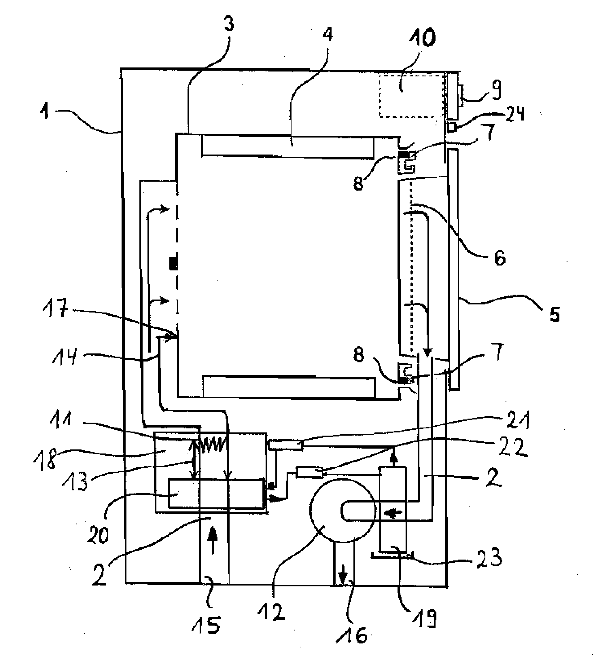
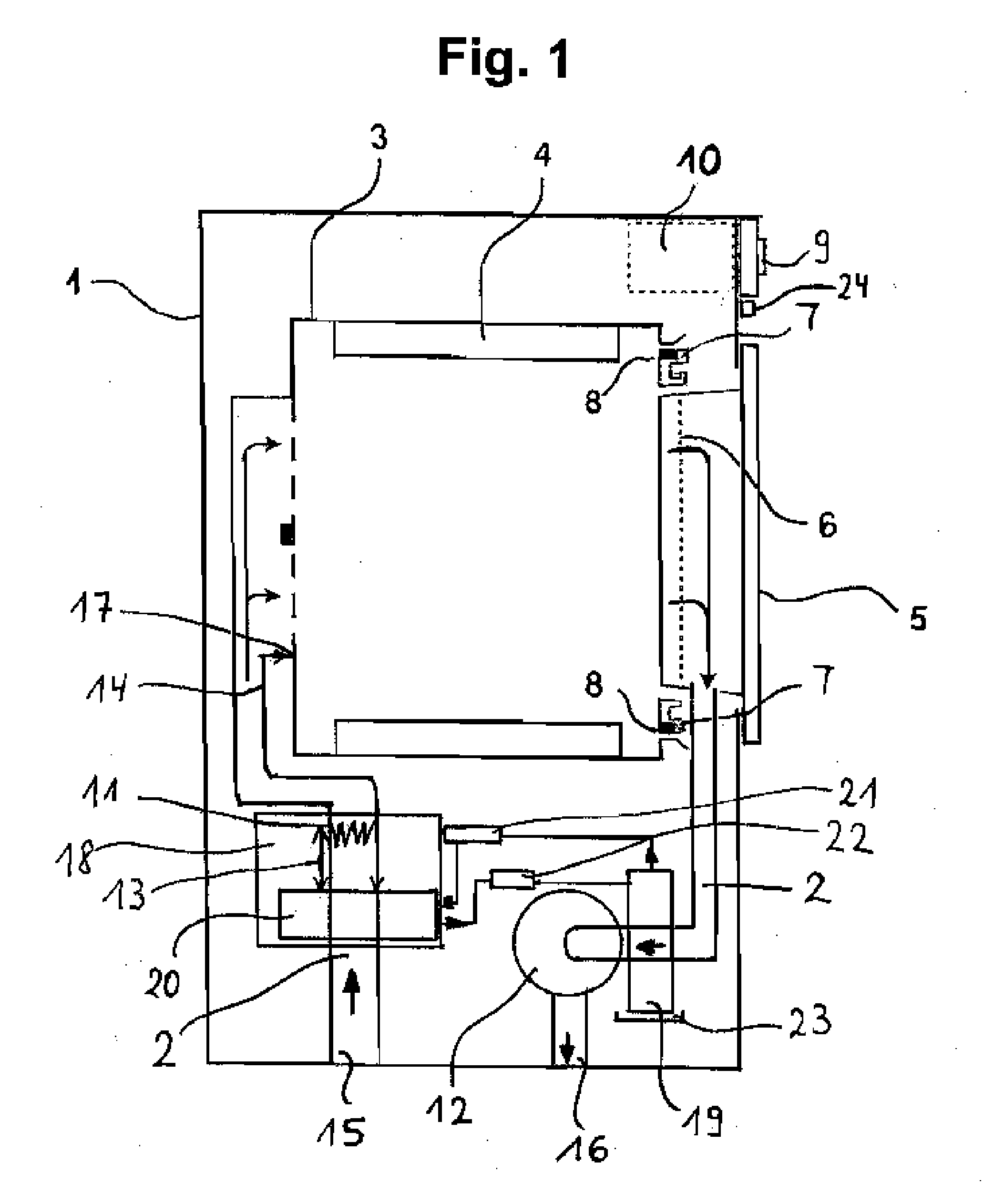
[0039]FIG. 1 shows a vertical section through a dryer 1 in which the dryer 1 is embodied as a vented-air dryer and a fan is arranged before an exhaust air outlet. The dryer 1 has a drum rotatable about a horizontal axis as its drying chamber 3, within which agitators 4 are attached for moving the washing during a drum rotation. Process air is conducted by means of a fan 12 starting from an inlet air entry 15 through the drum 3 and also a heat pump 19, 20, 21, 22 in a process air duct 2. After passing through the drum 3, the moist, warm process air is cooled and after condensation of the moisture contained in the process air in an evaporator 19 of the heat pump 19, 20, 21, 22, is directed via an exhaust air outlet 16 into the room where the dryer 1 is sited. The process air is heated up in this case with a condenser 20 of the heat pump 19, 20, 21, 22 and also an electrical heating element 11 arranged in its direct vicinity. The heated-up process air is directed from behind, i.e. fro...

second embodiment

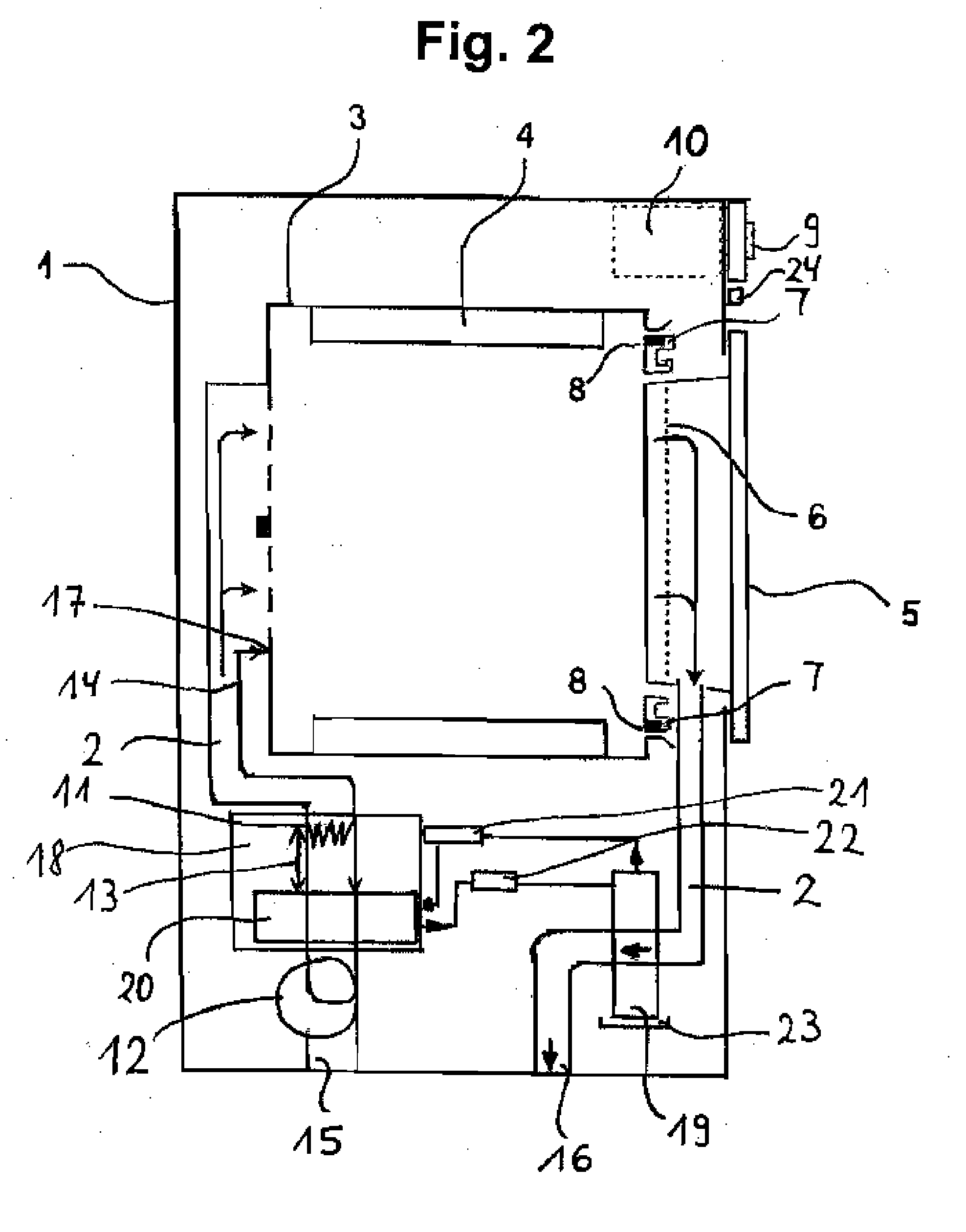
[0043]FIG. 2 shows a vertical section of a dryer 1 in which the dryer 1 is embodied as a vented-air dryer 1 and a fan 12 is arranged behind an inlet air access 15.

[0044]The single difference between the first embodiment shown in FIG. 1 and the second embodiment shown in FIG. 2 thus lies in the different arrangement of the fan 12. In FIG. 2. the fan 12 is namely located between an inlet air access 15 and the condenser 20.


PUM


Abstract

The invention relates to a dryer with a drying chamber for the items to be dried, a process air duct, a fan in the process air duct, a heat pump with a heat sink and a heat source thermally coupled to the process air duct, and also an electrical heating element. The electrical heating element is arranged in the direct vicinity of the heat source, with a first distance between the electrical heating element and the heat source being smaller than a second distance between the electrical heating element and an entry for the process air into the drying chamber. The invention also relates to a method for operating this dryer.

Description

BACKGROUND OF THE INVENTION[0001]The invention relates to a dryer with a drying chamber for the items to be dried, a process air duct, a fan in the process air duct, a heat pump with a heat sink and a heat source thermally coupled to the process air duct, and also to an electrical heating element, and also to a preferred method for its operation.[0002]A dryer is understood in this document to be a household appliance intended for drying specific items. In particular the dryer is a tumble dryer, a washer-dryer (i.e. a combination of a washing machine and a tumble dryer) or a dishwasher.[0003]Dryers of the generic type defined above, embodied in each case as tumble dryers, can be found in documents WO 2007 / 077084 A1, WO 2007 / 113081 A1, WO 2007 / 141166 A1, WO 2008 / 052906 A2, WO 2008 / 077792 A1 and WO 2008 / 086933 A1. In these cases the documents WO 2007 / 141166 A1 and WO 2008 / 086933 A1 relate to embodiments of a dryer in which a heat pump is combined with a normal electrical heating elemen...

Claims


Application Information

Patent Timeline
Patent Type & Authority Applications(United States)
IPC IPC(8): F26B3/02F26B25/06F27D11/00D06F58/30
CPCD06F58/02D06F58/26D06F58/206D06F58/30
Inventor KRAUSCH, UWE-JENSSTOLZE, ANDREAS
Owner BSH BOSCH & SIEMENS HAUSGERAETE GMBH
Why Eureka
Try Eureka