
Method and Device for Burning Hydrogen in a Premix Burner

a technology of hydrogen and premix burner, which is applied in the direction of combustion using catalytic materials, combustion types, combustion using lump and pulverulent fuel, etc., can solve the problems of increased nitrogen oxide emissions, unsuitable use of previously described premix burners, and increased risk of backflash, etc., and achieve stable flow conditions

Active Publication Date: 2008-11-13
ANSALDO ENERGIA SWITZERLAND AG
View PDF40 Cites 27 Cited by
  • Summary
  • Abstract
  • Description
  • Claims
  • Application Information

AI Technical Summary

Benefits of technology

[0011]Starting from this prior art, one of numerous aspects of the present invention includes a premix burner in which the above disadvantages do not occur, and which especially when operating with a fuel which contains hydrogen, with a hydrogen portion of at least 50 percent or with a gaseous fuel which exclusively consists of hydrogen, as the case may be, ensures an improved mixing through with the combustion air, and at the same time provides stable flow conditions.
[0014]In order to ensure a desirable clean and safe combustion of hydrogen, it is necessary to carry out the feed of hydrogen which is oriented axially and / or coaxially to the burner axis in such a way that on one hand the feed velocity of hydrogen is appreciably increased, and on the other hand the mixing through rate between hydrogen and combustion air is significantly increased. These measures lead to an appreciably improved homogeneity in the mixed through fuel-air mixture before achieving the flame front downstream of the burner.
[0017]The feed of hydrogen is carried out in such a way that as directly as possible after issue of the hydrogen from the feed pipes an efficient mixing through of the hydrogen with the combustion air takes place in order to avoid local hydrogen concentrations inside the burner, which are the cause of advanced ignition phenomena by way of spontaneous ignition. Furthermore, it is to be ensured that the average hydrogen retention time inside the burner is minimized as much as possible. This assumes that the axial through-flow velocity of the hydrogen-air mixture which is formed inside the burner is very high.

Problems solved by technology

On account of the high portion of hydrogen in the synthesis gas, and the low ignition temperature and high flame velocity of the hydrogen which are connected with it, there is a high reaction tendency of the fuel, which leads to an increased risk of backflash.
The combustion of medium-calorific fuels, the calorific values of which are typically between 5 MJ / kg and 15 MJ / kg, is indeed possible with the previously described burner concept in hybrid operating mode alone or in combination with the combustion of liquid fuel and natural gas, yet extensive combustion trials have revealed that, while endeavoring to use fuels which are as carbon-free as possible and which in addition have a hydrogen portion which is as large as possible and which preferably consist completely of hydrogen, the use of the previously described premix burner is not suitable.
Especially when using fuel which exclusively consists of hydrogen, high-pressure trials on a generic type premix burner for operating a gas turbine plant, the operation of which requires high firing temperatures, showed that ignition phenomena already occur in the swirl chamber or along the mixing path of the burner, as the case may be, which are attributed to an inadequate mixing of the hydrogen which is fed axialwards into the burner with large volumetric flow.
Even in cases in which no backflash phenomena occur, inadequate mixing of hydrogen and combustion air provides a diffusion-like combustion, which ultimately leads to increased emissions of nitrogen oxide.

Method used


Image

  • Method and Device for Burning Hydrogen in a Premix Burner
  • Method and Device for Burning Hydrogen in a Premix Burner
  • Method and Device for Burning Hydrogen in a Premix Burner

Examples


Embodiment Construction

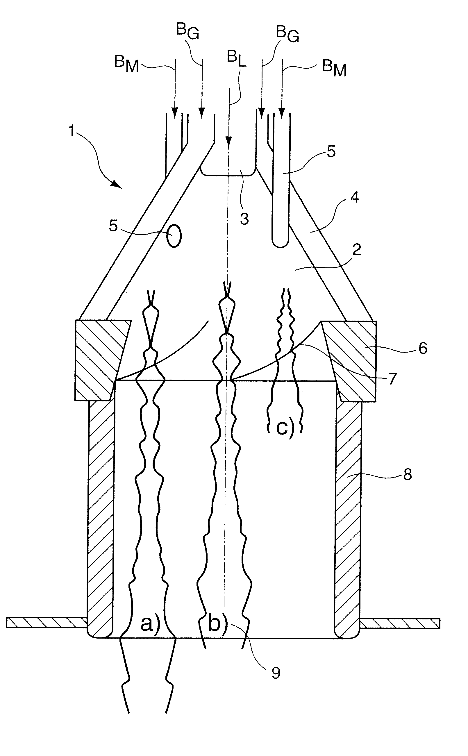
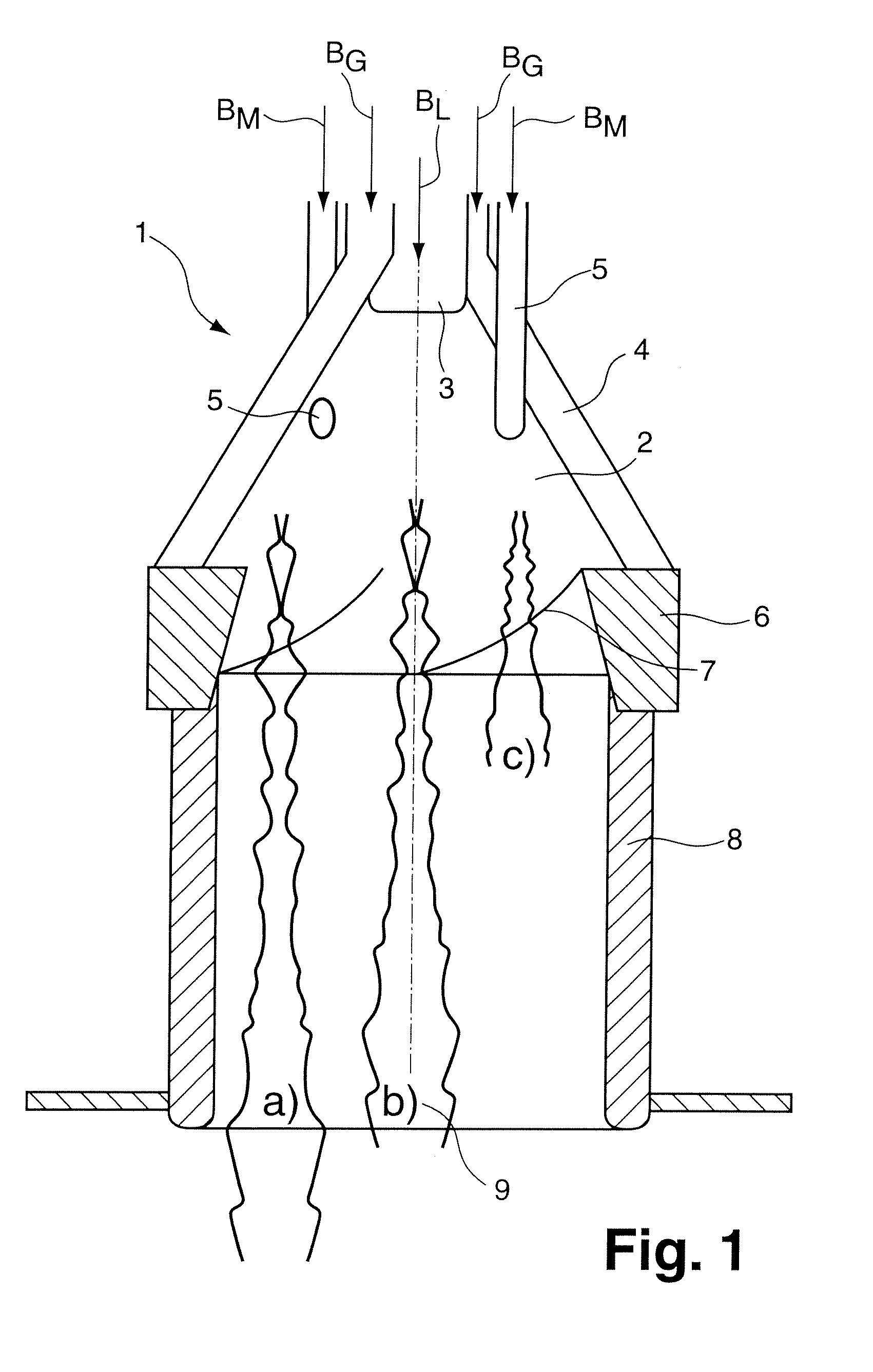
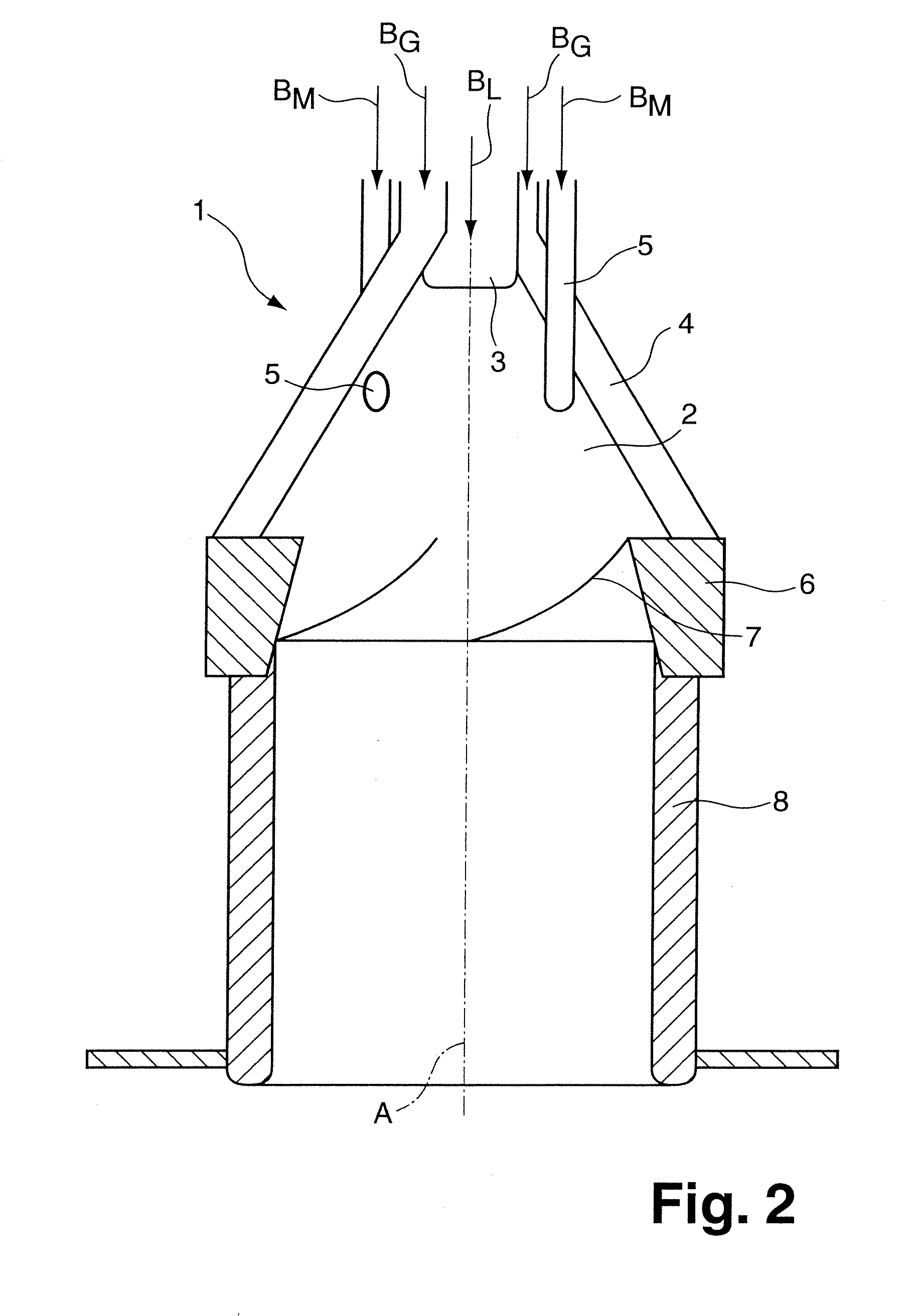
[0028]The ideal flow conditions which are formed inside the burner, under which hydrogen, or fuel which contains hydrogen, are to be fed into the inside of the burner, are to be explained in detail with reference to the longitudinal section which is shown in FIG. 1 through a premix burner with a swirl generator 1, a transition piece 6, and also a subsequent mixer tube 8. For feed of hydrogen, a multiplicity of feed pipes 5 are provided, of which only two are shown in FIG. 1, which are coaxially arranged around the burner axis A. The additional devices for feeding fuel, which are otherwise already described with reference to FIG. 2, are briefly referred to only for reasons of completeness. In this way, it is possible to inject liquid fuel, preferably crude oil BL, through a centrally disposed fuel nozzle 3, and similarly fuel pipes, which are provided along the air inlet slots 4, allow the feed of gaseous fuel BG, such as natural gas. Depending upon mode of operation and availability...


PUM


Abstract

A method and a device for combusting gaseous fuel which contains hydrogen or consists of hydrogen, includes a burner which provides a swirl generator (1) into which liquid fuel is feedable centrally along a burner axis (A), forming a liquid fuel column which is conically formed and which is enveloped by, and mixed through with, a rotating combustion air flow which flows tangentially into the swirl generator (1). The gaseous fuel is fed inside the swirl generator (1) largely axially and / or coaxially to the burner axis (A), forming a fuel flow with a largely spatially defined flow pattern (9) which is maintained inside the burner and bursts open in the region of the burner outlet.

Description

[0001]This application is a Continuation of, and claims priority under 35 U.S.C. § 120 to, International application number PCT / EP2005 / 055985, filed 15 Nov. 2005, and claims priority therethrough under 35 U.S.C. § 119 to Swiss application number 01971 / 04, filed 30 Nov. 2004, the entireties of which are incorporated by reference herein.BACKGROUND[0002]1. Field of Endeavor[0003]The invention relates to a method and also a device for combusting gaseous fuel, which contains hydrogen or consists of hydrogen, with a burner which provides a swirl generator into which liquid fuel, for example mineral oil, is feedable centrally along a burner axis, forming a liquid fuel column which is conically formed, and which is enveloped by, and mixed through with, a rotating combustion air flow which flows tangentially into the swirl generator. Furthermore, devices for feeding gaseous fuel, for example natural gas, are provided in the combustion air flow which enters the swirl generator through tangent...

Claims


Application Information

Patent Timeline
IPC IPC(8): F23C5/32F23D14/02F23C6/02F23C7/00
CPCF23C7/002F23C13/00F23C2900/07002F23C2900/9901F23D14/02F23D17/002
Inventor CARRONI, RICHARDGRIFFIN, TIMOTHY
Owner ANSALDO ENERGIA SWITZERLAND AG
Learn More