Plug-in sensor having an optimized flow outlet

a plug-in sensor and flow outlet technology, which is applied in the direction of engine testing, structural/machine measurement, instruments, etc., can solve the problems of contaminating the sensor element, affecting the flow rate of the plug-in sensor, and affecting the flow rate of the sensor, so as to maximize the flow rate of the flowing fluid medium, reduce the magnitude of the detachment area on the plug-in part, and stabilize the flow conditions

Active Publication Date: 2011-01-06
ROBERT BOSCH GMBH
View PDF24 Cites 8 Cited by
  • Summary
  • Abstract
  • Description
  • Claims
  • Application Information

AI Technical Summary

Benefits of technology

[0026]This design of the at least one outlet opening, in one of its described variants, has the additional advantage of maximizing the throughput of the flowing fluid medium, particularly through the bypass channel. The outer flow of the fluid medium about the plug part is disturbed only minimally. The magnitude of the detachment areas on the plug part may also be minimized, particularly by a suitable design of the at least one main flow outlet, whereby more stable flow conditions about the plug part set in. Overall, the signal noise of the measuring signal of the plug part is considerably improved, and the reproducibility of the measuring signal is increased.

Problems solved by technology

One problem with such a type of conventional sensor described in German Patent Application No.
DE 101 11 840 C2, for instance, is that contamination of the sensor element may often occur, such as contamination by water, oil or other fluids, or other types of soiling.
This soiling deposit can lead to an undesired effect on the measuring signal of the sensor, especially since a fluid film on the surface of the sensor affects the thermal conductivity of the surface, which results in a falsification of the measuring signals.
Besides in hot film air mass meters, similar problems also occur in other types of sensors, which are used for measuring fluid parameters in a fluid flow.
However, in the conventional plug-in sensor constructions, it is disadvantageous that the plug-in sensors, because of their aerodynamically unfavorable shape, in many cases cause problems in the intake tract, with regard to a flow resistance-conditioned loss in pressure.
In addition, the signal reproducibility of such sensors is comparatively low.
One disadvantage is, for instance, that the flow-diversion part is, generally, fixedly installed in a section of the flow pipe.
This fixed installation brings on additional costs in the manufacture of these pipe sections, just as does the provision of the additional flow-conducting wall.
In the development as one piece, the installation length is also too long for many applications.
Further problems are that the construction described in German Patent Application Nos.
DE 101 35 142 A1 or DE 10 2004 022 271 A1 has only a comparatively low air mass throughput through the bypass channel, so that overall the signal level swings (and, with that, also the signal to noise ratio) are often comparatively unsatisfactory.
In the case of optimal positioning of the at least one outlet opening it has turned out, however, that still one more considerable disturbance of the surrounding flow of the plug part is able to take place by outflowing fluid medium from the at least one outlet opening.
This works out disadvantageously on the pressure drop at the plug-in sensor and on the signal properties.

Method used


Image

  • Plug-in sensor having an optimized flow outlet
  • Plug-in sensor having an optimized flow outlet
  • Plug-in sensor having an optimized flow outlet

Examples


Embodiment Construction

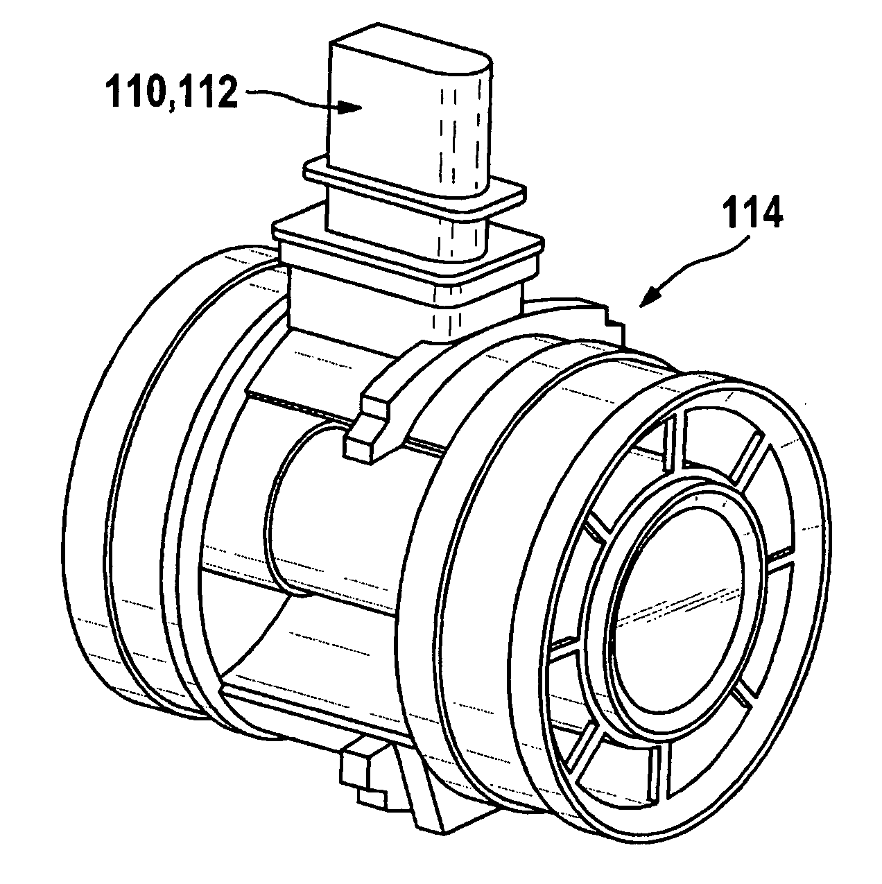
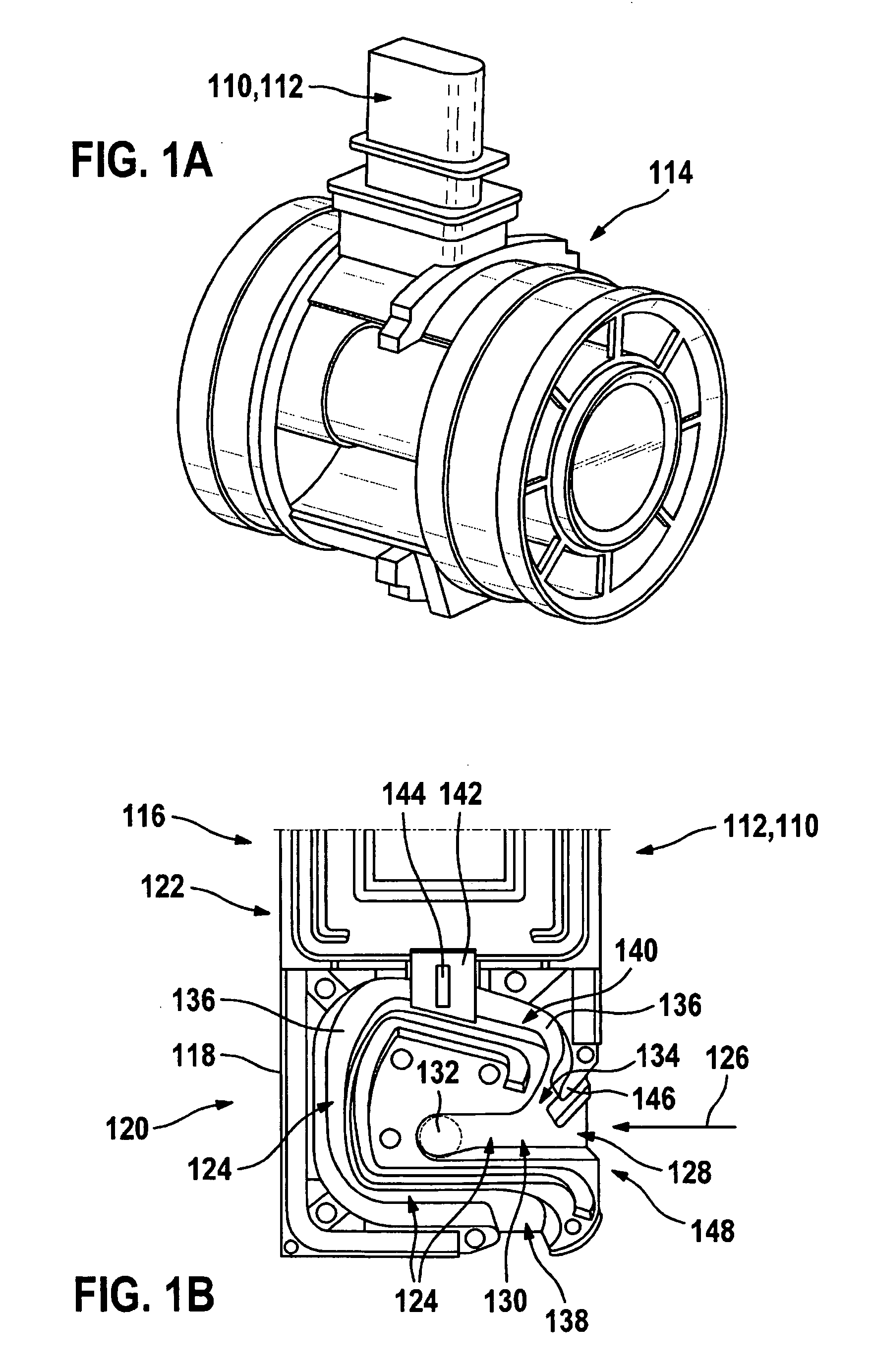
[0039]FIG. 1A shows an exemplary embodiment of a conventional plug-in sensor 110, which, in this case, is developed as a hot film air mass meter 112. Hot film air mass meter 112 is inserted into an intake tract 114 of an internal combustion engine, which is not shown in FIG. 1A. Such hot film air mass meters 112 are commercially available. Hot film air mass meter 112 is designed to detect the flow direction of an intake flow and is designed to record the load in internal combustion engines, using gasoline or Diesel fuel injection. The installation of hot film air mass meter 112 is usually made between an air filter and a throttling device, and it is usually installed as a preassembled assembly. Accordingly, plug-in sensor 110 has a plug part 116, which is shown in FIG. 1B in an opened state in a side view, and which projects in FIG. 1A into intake tract 114. It may be seen in FIG. 1B that, in this exemplary embodiment of hot film air mass meter 112, a measuring housing 118 of hot fi...


PUM


Abstract

A plug-in sensor is provided which is suitable for determining at least one parameter of a fluid medium flowing in a main flow direction, especially of an intake air mass of an internal combustion engine flowing through a flow pipe. The plug-in sensor has a plug part that is able to be mounted in the flowing fluid medium, in a specified alignment to the main flow direction. In the plug part, at least one flow channel is provided having at least one inlet opening and at least one outlet opening, in the at least one flow channel at least one sensor is accommodated for determining the at least one parameter. The plug part has a profile at which at least one local pressure minimum sets in the flowing fluid medium. The at least one outlet opening is situated at the side of the plug part, in the region of the at least one pressure minimum.

Description

FIELD OF THE INVENTION[0001]The present invention relates to a device for measuring at least one parameter of a flowing fluid medium, in particular, a fluid medium flowing through a flow pipe.BACKGROUND INFORMATION[0002]In many processes, for instance, in the field of industrial processing engineering, chemistry or machine construction, fluid media, especially masses of gas (e.g. an air mass) having particular properties (such as temperature, pressure, flow speed, mass flow, etc.) have to be supplied in a defined manner. Among these are, in'particular, combustion processes, which run under regulated conditions.[0003]An important application example is the combustion of fuel in internal combustion engines of motor vehicles, especially ones having subsequent catalytic exhaust gas purification, in which a certain air mass has to be supplied per unit time in a controlled manner (air mass flow). Various types of sensors are used to measure the air-mass throughput. One conventional sensor...

Claims


Application Information

Patent Timeline
Patent Type & Authority Applications(United States)
IPC IPC(8): G01F1/684
CPCG01F1/6842G01F5/00
Inventor KONZELMANN, UWEGMELIN, CHRISTOPH
Owner ROBERT BOSCH GMBH
Why Eureka
Try Eureka