
Routing Device

a routing device and routing technology, applied in the field of routing devices, can solve the problems of limiting the call-acceptance performance of the network, unable to guarantee the service of the network, and adding more buffers can apparently control loss, so as to reduce delay and maximize effective throughput

Inactive Publication Date: 2006-02-28
GOS HLDG LTD
View PDF9 Cites 88 Cited by
  • Summary
  • Abstract
  • Description
  • Claims
  • Application Information

AI Technical Summary

Benefits of technology

[0057]It is preferred that in a system according to the present invention queue sizes may be controlled in order to maximise effective throughput and reduce delay. Packet losses may preferably be balanced against throughput and delay. The network can then preferably run at full or substantially full utilisation whatever the demand upon it, up to a limit imposed by the network's capacity.

Problems solved by technology

One problem in such networks is to be able to constrain the quantity of data admitted into the network in order to provide a good level of overall service.
In the first case no guarantees of service can be offered by the network, only promises to treat some packets relatively better than others; while in the second case the centralised process limits the call-acceptance performance of the network.
Adding more buffers can apparently control loss.
There is a penalty for this because the additional buffers introduce further delays and can lead to retransmission of traffic, and this then increases the congestion even more.
Adding more buffers can apparently control loss.
There is a penalty for this because the additional buffers introduce further delays and can lead to retransmission of traffic, and this then increases the congestion even more.
However there is no simple method currently described for deciding whether to admit a call considering both its loss and delay requirements exploiting the flexibility offered by the combination of these techniques.
Transfers can be aborted due to delay tolerance being exceeded.
However, only performance at a single node is addressed, not end-to-end performance.
None of these systems considers both loss and delay in their QoS decision-making.
EP 0 828 362 A describes a system that uses a central network controller for CAC (call admission control), and does not provide guarantees for the duration of a connection.

Method used


Image

  • Routing Device
  • Routing Device
  • Routing Device

Examples


Embodiment Construction

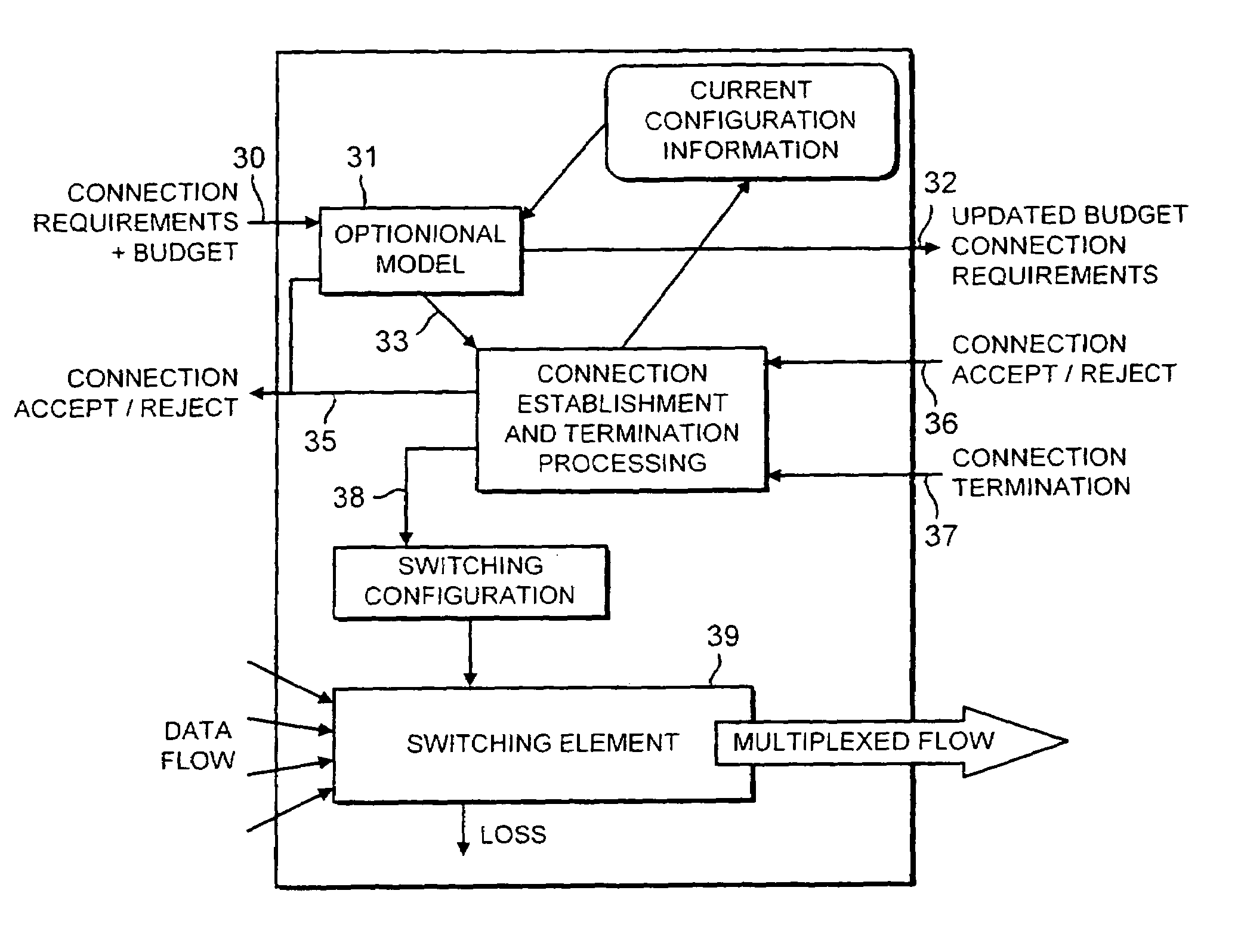
[0088]Admitting a call or generally a data stream into a network requires confidence that the interaction between that call's traffic and existing traffic is benign. In making service level agreements this principle is given a monetary value. In this paper we describe the application of a probabilistic approach to call management. This model can be used to derive very conservative performance bounds where this is required, or to evaluate the dynamic probabilities of meeting particular service levels.

[0089]A large class of network applications, particularly real time applications such as telephony, can only operate satisfactorily when a network can reliably provide quality of service. This requires the ability for applications, directly or indirectly, to negotiate with the network to ensure that network delays do not impinge on the application's functionality.

[0090]The product of these negotiations are Service Level Agreements; they define the acceptable Quality of Service in terms w...


PUM


Abstract

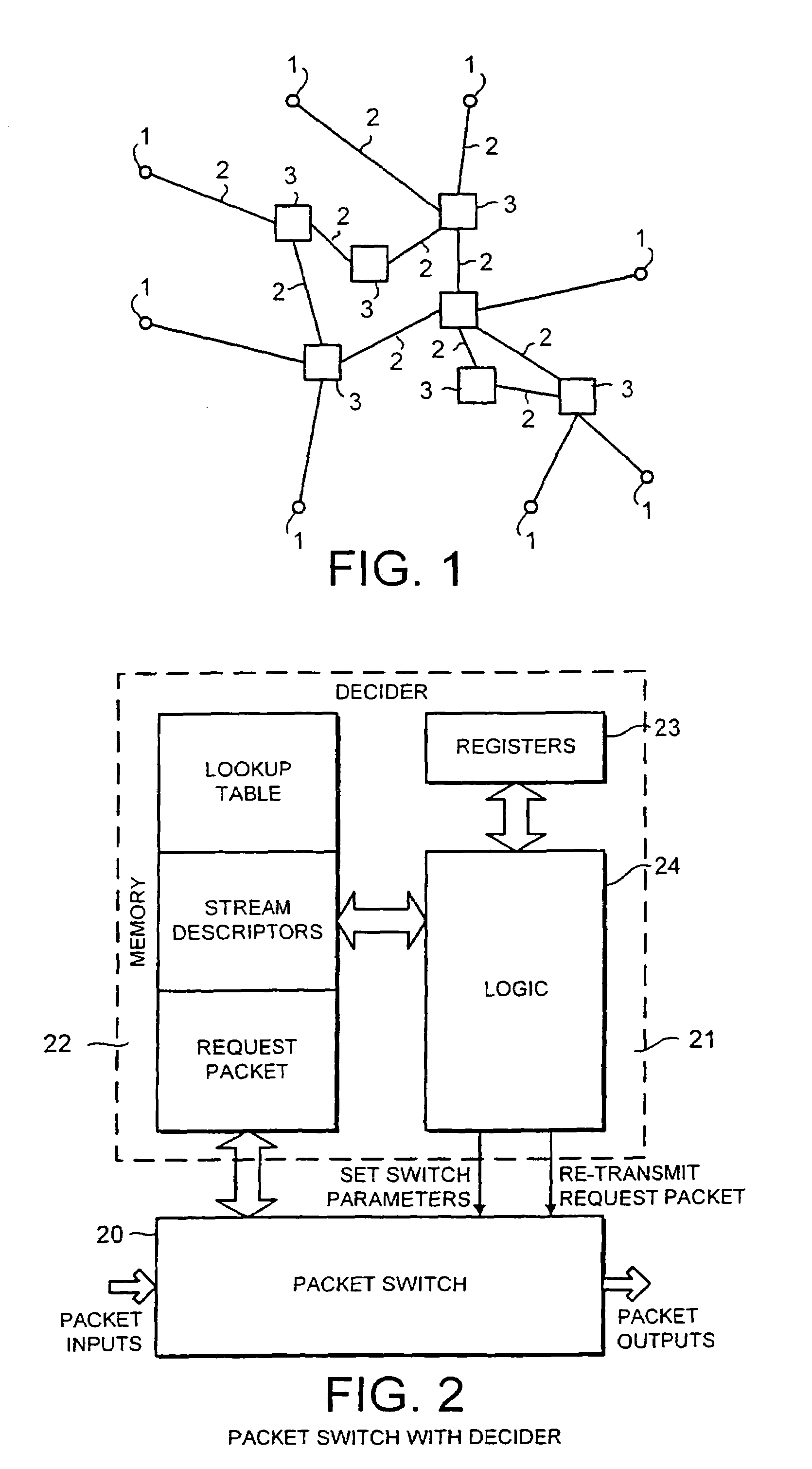
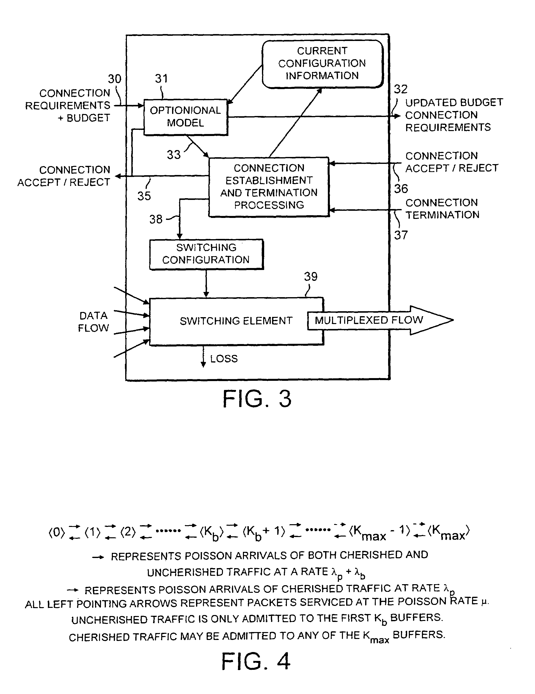
A routing device for routing streams at a node in a packet transmission network receives a stream request, reads specified parameters and any values for loss and delay already incurred at preceding nodes in the network, or specified parameters as modified to take account of loss and delay already incurred at preceding nodes in the network, to determine in conjunction with existing streams already being handled by the routing device whether to accept or reject the stream, allocates one or more buffers to the stream if the stream request has been accepted, transmits the stream request with modified values for loss and delay, or with modified parameters to take account of loss and delay incurred at this and preceding nodes in the network if the stream request has been accepted, and returns a fail signal if the stream request has been rejected.

Description

BACKGROUND OF THE INVENTION[0001]1. Field of the Invention[0002]The present invention relates to routing devices for data transmission networks, and especially to routing devices having a capability to make decisions.[0003]2. Description of the Related Art[0004]Communication networks in which data is transferred from a source to a destination in packets, each packet being sent in a series of steps from one component in the network to the next until it reaches its destination, are well known. Some such networks attempt to deliver guarantees of bandwidth and specific limits on the delay that packets experience and the proportion of them that must be discarded during periods of congestion.[0005]One problem in such networks is to be able to constrain the quantity of data admitted into the network in order to provide a good level of overall service. One solution to this problem is to allow a source to introduce a series of packets of data into the network only after a request to do so ha...

Claims


Application Information

Patent Timeline
IPC IPC(8): H04L12/26H04L1/00H04L49/111H04Q11/04
CPCH04L1/0001H04L1/0017H04L49/205H04L49/253H04L49/309H04Q11/0478H04L2012/562H04L2012/5651H04L2012/5679H04L2012/5682H04L49/50
Inventor DAVIES, NEIL JAMESHOLYER, JUDITH YVONNETHOMPSON, PETER WILLIAMBRADLEY, JEREMY THOMASFRANCIS-COBLEY, PAULINE PATRICIA
Owner GOS HLDG LTD
Learn More