Vision based conveyor package flow management system

a technology of conveyor package and flow management system, applied in the field of vision systems, can solve problems such as the need for stoppage of feed lines, and achieve the effect of maximizing the flow of packages

Active Publication Date: 2016-08-04
FIVES INTRALOGISTICS SA
View PDF2 Cites 92 Cited by
  • Summary
  • Abstract
  • Description
  • Claims
  • Application Information

AI Technical Summary

Benefits of technology

[0011]Cameras positioned to view the singulator surface are used in a similar matter to assess the buffer capacity utilization, primarily based on area coverage recognition. This feedback is used to dynamically adapt behavior of infeed lines. The use of web cams provides added benefits in terms of system control room visibility and recordation. Variations in parameters used to tune the system can be evaluated in a more efficient manner. Jams and other system problems are better recognized.
[0012]A plurality of cameras in communication with a computer based conveyor package management system includes video cameras monitoring the number and size of the packages present a given area of an infeed conveyor, collector conveyor, singulator conveyor and sorting conveyor in a package handling system wherein the camera data is collected and analyzed to measure the available area or space on the conveyors and the density of packages thereon to maximize a desired density of packages on selected conveyor(s). The number of feed conveyors providing packages and the conveyor speed of each is controlled as a function of occupancy on a collector or just prior to a singulator. The computer feeds the camera package density information to the conveyor speed controllers to introduce packages from one or more feed conveyors to a collection conveyor wherein packages are detected by one or more cameras and the speed of selected conveyors is controlled for arrangement of the packages at optimal spacing and to fill an area of the conveyor in the most efficient manner maximizing the density of the packages on a conveyor and throughput of the system and accordingly minimizing the number of conveyors required for the system. When the computer determines there is a enough space on one of the conveyor belts, for example, the collector belt, the computer tells the controller to add a package or packages by causing an infeed belt to add a package or packages to the space or vacant area on the collector belt.
[0016]It is an object of this invention to provide a video based conveyor package management system which includes video cameras which monitor the packages at the merge areas of the infeed conveyors, all along the collector conveyor, the singulator conveyor and the sorter, identifying areas of low density and controlling the activation and speed of selected conveyors to increase the density of items of a given area of a conveyor.
[0022]It is an object of this invention to provide a video based conveyor package management system which regulates input flow to a conveyor system where a camera is placed at each source of input to a collector conveyor, allowing control of the speed of each input conveyor with respect to the speed of the collector conveyor to the maximize the flow of packages through the system.

Problems solved by technology

These measures can be used to make changes to reduce parcel input flow, and could require stoppage of the feed line, if flow is too sparse or dense.

Method used


Image

  • Vision based conveyor package flow management system
  • Vision based conveyor package flow management system
  • Vision based conveyor package flow management system

Examples


example 1

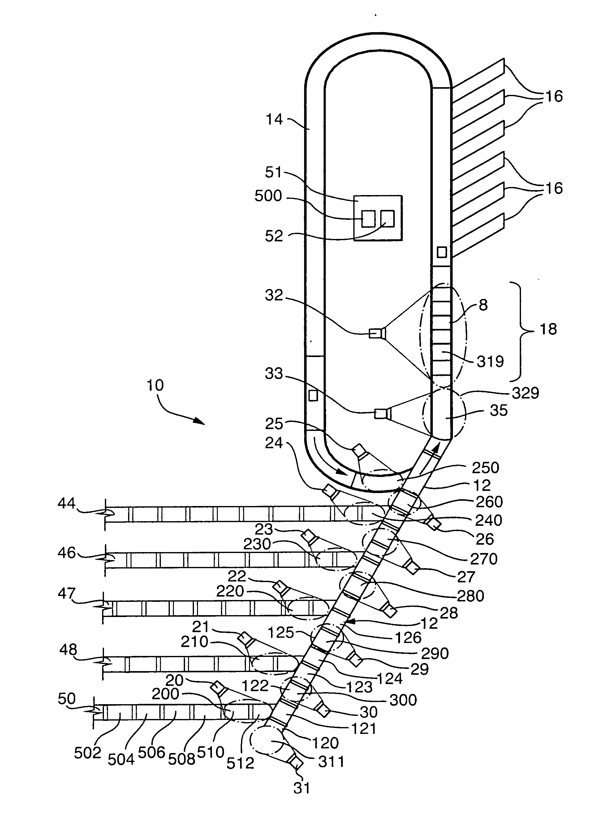
[0073]As shown in FIG. 8 packages are off loaded from a cargo carrier onto a selected induction feed conveyor 44, 46, 47, 48, and 50 in flow communication with a collector conveyor 12 composed of modular units of sections of conveyor 120-134. For example, induction feed conveyor 50 intersects with and feeds articles onto collector conveyor section 121, induction feed conveyor 48 intersects with and feeds articles onto collector conveyor section 124, induction feed conveyor 47 intersects with and feeds articles onto collector conveyor section 127, feed conveyor 46 intersects with and feeds articles onto conveyor section 129, and feed conveyor 44 intersects with and feeds articles onto collector conveyor section 132. The recycling or recirculating conveyor 14 intersects with and feeds into conveyor section 134.

[0074]In accordance with FIG. 9, the collecting conveyor 12 starts at the first feed conveyor 50 and extending to an accumulator 35 and / or singulator 8 intersecting a selected n...

example 2

[0087]The vision based package flow management control system can be utilized with a variety of sorting and alignment conveyors such as a singulator.

[0088]One preferred conveyor system according to the present invention is depicted schematically in top plan view in FIG. 17-26. Depicted therein is the downstream end of the singulator conveyor 310 which has skewed rollers 312 for advancing articles, such as packages, in a direction having a longitudinal forward component L and a lateral inward component L′. The packages are advanced forwardly while being arranged in single file against a vertical side wall 316.

[0089]It is necessary that side by side packages be removed in order to avoid the situation where two packages travel simultaneously to a scanner mechanism. In order to prevent such an occurrence, one embodiment of the present utilizes a removal conveyor 340 positioned between the singulator conveyor 310 and the flow control mechanism 320.

[0090]The removal conveyor comprises a v...


PUM


Abstract

A camera based vision system that recognizes and maximizes belt area utilization. A plurality of cameras are positioned at flow entry points of feed conveyors and at the singulator. The control algorithm recognizes individual items area, the rate at which individual objects are passing, and the area utilization of the collector belt. The video camera and computer based conveyor package management system monitor and control the number and size of the packages present on the infeed conveyors, collector conveyor, singulator conveyor and sorting conveyor in a package handling system wherein the camera data is used to measure the available area or space on the conveyors to maintain a desired density of packages on selected conveyor(s). The conveyor speed is controlled as a function of occupancy on a collector or just prior to a singulator or receiver.

Description

CROSS REFERENCES TO RELATED APPLICATIONS[0001]This application claims priority from U.S. Provisional Application Ser. No. 62 / 124,735 filed on Dec. 31, 2014 which is incorporated by reference in its entirety.TECHNICAL FIELD[0002]The present invention relates to the field of vision systems used to enhance the performance and throughput of conveyor systems.BACKGROUND OF THE INVENTION[0003]Conveying systems often serve the function of aligning and spacing articles on the conveying system to be processed by a downstream sorting system. Conventional conveyance systems typically involves controlling the articles in such a way that the articles leaving the induction subsystem have gaps between them that are close to a desired length. The desired gap may be variable depending upon the length and / or width of one or more of the pair of articles that define the gap, or the desired gap may be constant. Regardless of the criteria used to determine the length of the desired gap, the gap serves the...

Claims


Application Information

Patent Timeline
Patent Type & Authority Applications(United States)
IPC IPC(8): B65G43/08G06K9/00B65G47/31
CPCB65G43/08B65G47/31B65G2811/0673B65G2203/041B65G43/10B65G47/681G06K9/00771G06V20/52G06V2201/06G06V30/424
Inventor SCHROADER, STEVEN VANN
Owner FIVES INTRALOGISTICS SA
Why Eureka
Try Eureka