Base station apparatus and method for controlling transmission assignment
- Summary
- Abstract
- Description
- Claims
- Application Information
AI Technical Summary
Benefits of technology
Problems solved by technology
Method used
Image
Examples
embodiment 1
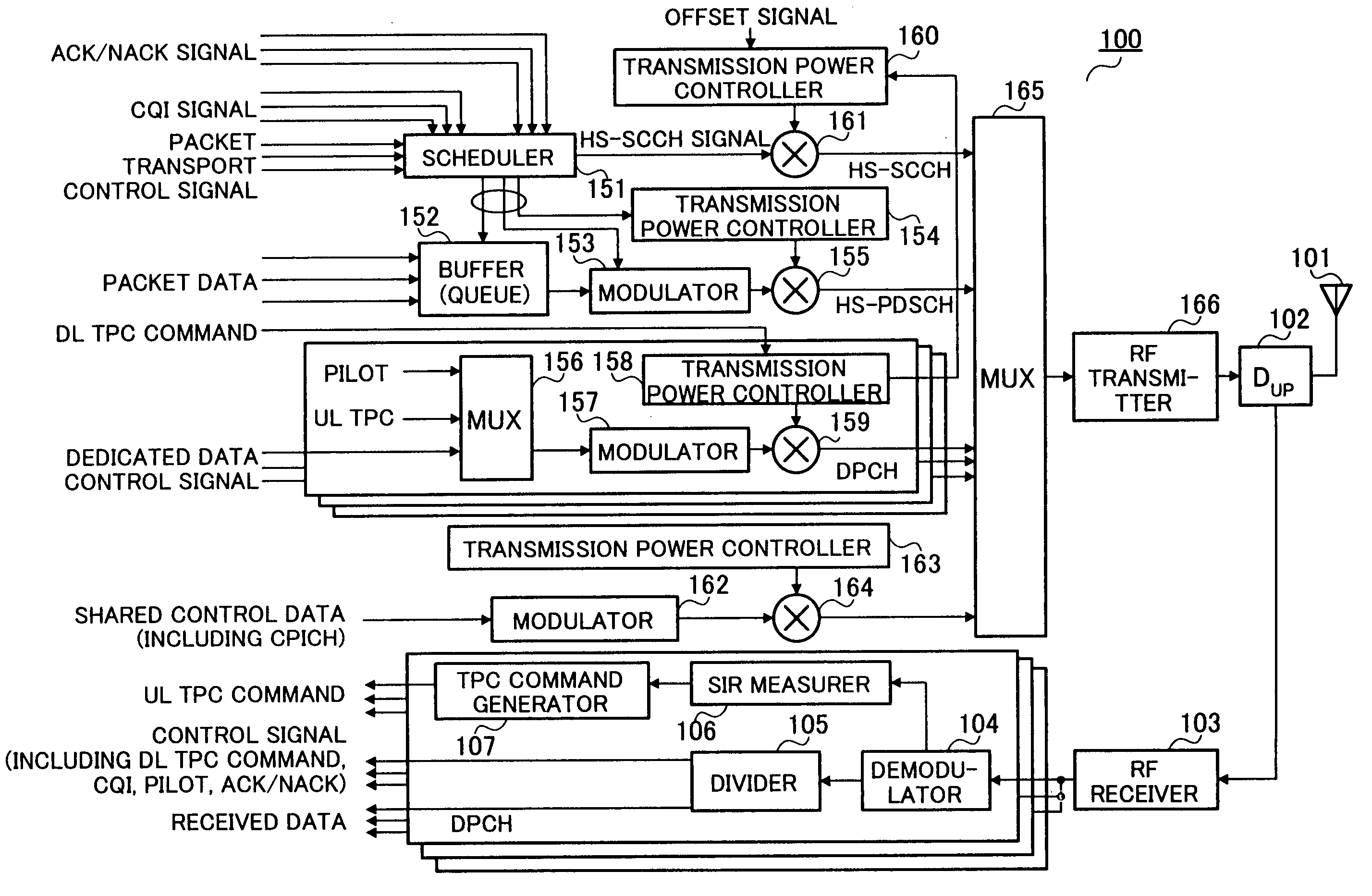
[0042]FIG. 3 is a block diagram showing a configuration of a base station apparatus according to Embodiment 1 of the present invention. The functions of the individual components of base station apparatus 100 shown in FIG. 3 will be described below.
[0043] Duplexer (DUP) 102 outputs a signal received by antenna 101 to RF receiver 103. In addition, duplexer 102 transmits a signal output from RF transmitter 166 by radio from antenna 101.
[0044] RF receiver 103 converts the received signal of radio frequency output from duplexer 102 into a baseband digital signal, and outputs the result to demodulator 104.
[0045] Demodulator 104 performs demodulation processing upon the received baseband signal including despreading, RAKE combining, and error correction decoding, and outputs the result to divider 105. Divider 105 divides the output signal from demodulator 104 into the data and the control signal.
[0046] The control signal separated in divider 105 includes a DL (Down Link)-TPC command, ...
embodiment 2
[0104] Although the first embodiment has been described using the same TBS table for initial transmission and retransmission without distinguishing between them, the present embodiment will be described with reference to a TBS table that takes retransmission, IR-scheme retransmission in particular, into consideration.
[0105]FIG. 10A is a table with specific TBS values. FIG. 10B shows code rates corresponding to the TBS. For ease of explanation, the number of codes shown is between 1 and 5. In FIG. 10B, most of the code rates are above 0.6 and below 1, and, in comparison to the code rates of FIG. 8, the code rates are limited.
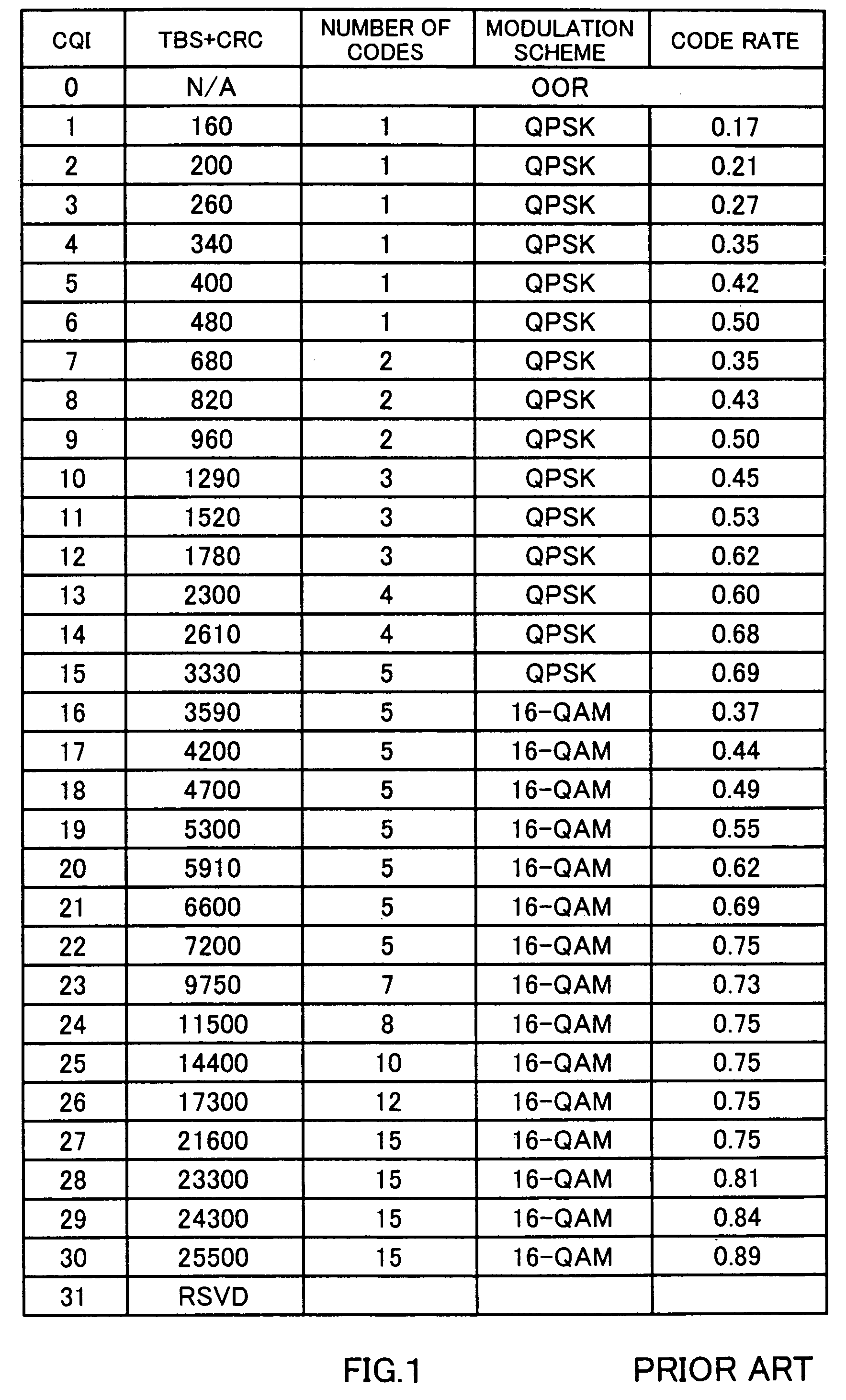
[0106]FIG. 11 shows a comparison of a conventional CQI table and the above-described TBS table. The figure presents a graph in which the vertical axis represents the TBS [bit] and the horizontal axis represents the HS-PDSCH SIR [dB]. The broken line connecting the plots of circles represents the conventional CQI table and the broken line connecting the plots of...
embodiment 3
[0117] A case will be described here with this embodiment where the TBS is adjusted in consideration of the amount of data awaiting transmission in a buffer (Queue).
[0118]FIG. 13 is a block diagram showing the internal configuration of the scheduler according to Embodiment 3 of the present invention.
[0119] Parts in FIG. 13 that are identical to the ones in FIG. 5 are assigned the same numerals as in FIG. 5 without further explanations.
[0120] The difference between FIG. 13 and FIG. 5 is that MCS determiner 304 is replaced by MCS determiner 1101.
[0121] Buffer 152 counts the amount of data awaiting transmission (referred to as “the amount of data in queue”) and reports the result to MCS determiner 1101.
[0122] MCS determiner 1101 performs control such that the TBS does not exceed the amount of transmission data by more than a certain range in consideration of the amount of data in queue. For example, when the HS-PDSCH SIR is good and a TBS candidate is determined that exceeds the a...
PUM
 Abstract
Description
Claims
Application Information
 - R&D
- Intellectual Property
- Life Sciences
- Materials
- Tech Scout
- Unparalleled Data Quality
- Higher Quality Content
- 60% Fewer Hallucinations
Browse by: Latest US Patents, China's latest patents, Technical Efficacy Thesaurus, Application Domain, Technology Topic, Popular Technical Reports.
© 2025 PatSnap. All rights reserved.Legal|Privacy policy|Modern Slavery Act Transparency Statement|Sitemap|About US| Contact US: help@patsnap.com


