Device and method for pressure-driven plug transport and reaction

a plug and plug technology, applied in the field of microfluidics, can solve the problems of inability to provide high-voltage sources such as portable analyzers, serious limitations, and inability to achieve high-voltage effects, and achieve the effect of evaporating solutions

Inactive Publication Date: 2010-09-16
ISMAGLIOV RUSTEM F +3
View PDF37 Cites 158 Cited by
  • Summary
  • Abstract
  • Description
  • Claims
  • Application Information

AI Technical Summary

Benefits of technology

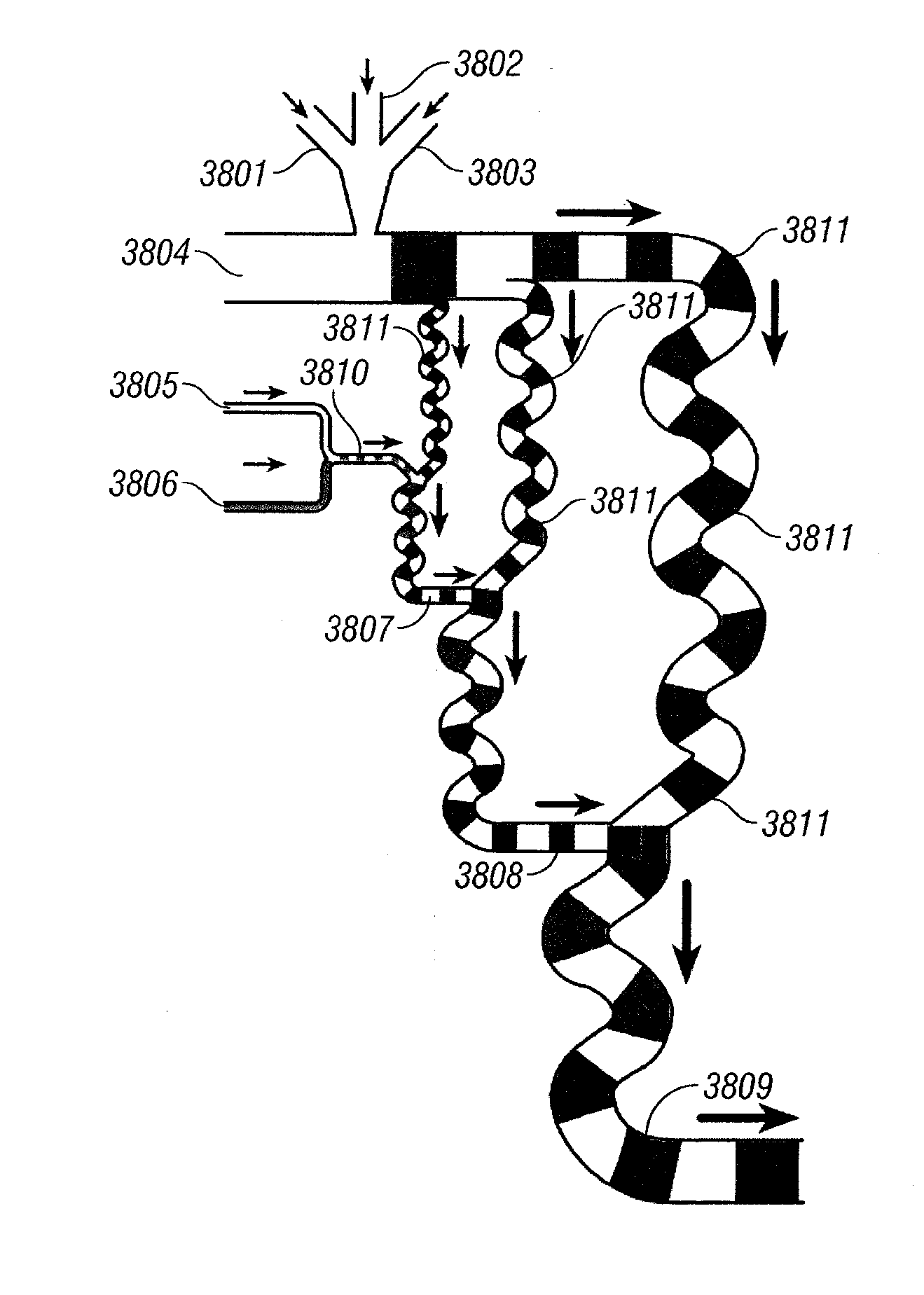
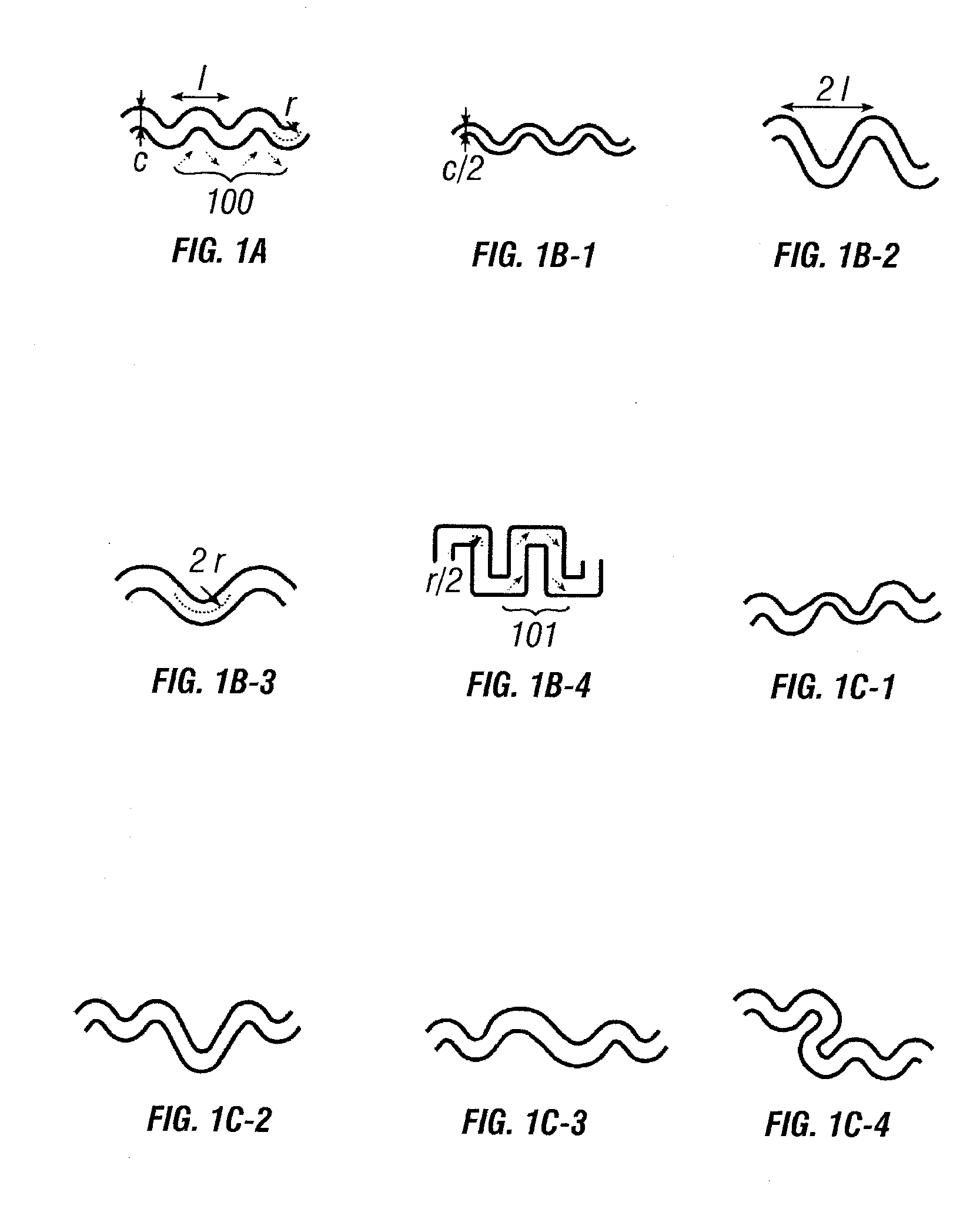
[0011]When plugs are formed from more than one plug-fluid, the fluids are rapidly mixed. Mixing inside plugs is further enhanced when the channels are not straight (i.e., when chaotic flows are generated). Aperiodic channel designs are preferred to induce rapid mixing within plugs. In other cases, mixing can be slowed down or controlled such as by using winding channels, varying the fluid viscosities, varying the plug-fluid composition, and twirling, which can also be controlled.
[0017]Crystallization devices can further include capillary tubing used to collect the plugs, to allow for direct detection of crystallization and to eliminate evaporation of solutions during crystallization.

Problems solved by technology

A main disadvantage of EOF is that it is generated by the motion of the double layer at the charged surfaces of the channel walls.
However, this can be a serious limitation in applications that involve proteins that are often charged and tend to adsorb on charged surfaces.
In addition, high voltages are often undesirable, or sources of high voltages such as portable analyzers may not be available.
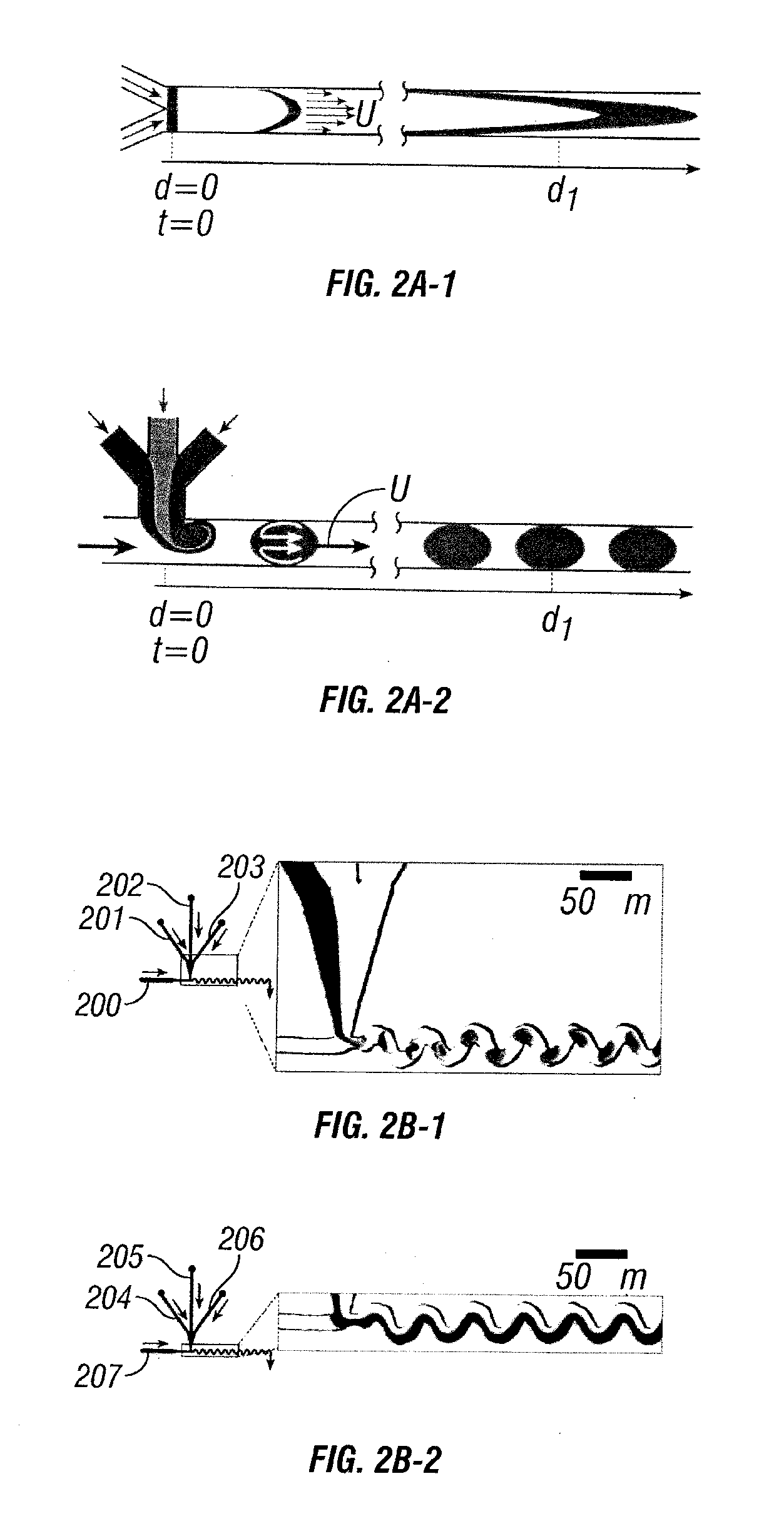
The main disadvantage of pressure-driven flows is that they normally have a parabolic flow profile instead of the flat profile of EOF.
Overlap of these tails usually leads to cross-contamination of samples in different plugs.
On the other hand, interleaving samples with long buffer plugs, or washing the system with buffer between samples, reduces the throughput of the system.
In contrast, dispersion in pressure-driven flow typically creates a broad range of residence times for a plug traveling in such flows, and this diminishes time control.
So far, microfluidic devices have not be able to compete with stopped-flow type instruments because EOF is usually very slow (although with less dispersion) while pressure-driven flows suffer from dispersion.
In addition, mixing in microfluidic systems is often slow regardless of the method used to drive the fluid because flow is laminar in these systems (as opposed to turbulent in larger systems).
Mixing in laminar flows relies on diffusion and is especially slow for larger molecules such as DNA and proteins.
In addition, particulates present handling difficulty in microfluidic systems.

Method used


Image

  • Device and method for pressure-driven plug transport and reaction
  • Device and method for pressure-driven plug transport and reaction
  • Device and method for pressure-driven plug transport and reaction

Examples


example

Example 1

Fabrication of Microfluidic Devices and a General Experimental Procedure

[0363]Microfluidic devices with hydrophilic channel surfaces were fabricated using rapid prototyping in polydimethylsiloxane. The channel surfaces were rendered hydrophobic either by silanization or heat treatment. To silanize the surfaces of channels, (tridecafluoro-1,1,2,2-tetrahydrooctyl)-1-trichlorosilane (United Chemical Technologies, Inc.) vapor was applied to the inlets of a device with dry nitrogen as a carrier gas at around 40-60 mm Hg above about 1 atm pressure. Vacuum was simultaneously applied to the outlet of the device at about 650 mm Hg below atmospheric pressure. The silane vapor was applied for a period of between about 1-3 hours. To treat the channels using heat, a device was placed in an oven at approximately 120° C. for about three hours. Alternatively, a device can be heated in a Panasonic “The Genius” 1300 Watt microwave oven at power set to “10” for about ten minutes.

[0364]Oils an...

example 2

Varying the Concentration of Aqueous Solutions in Plugs

[0367]The left side of each of FIGS. 25A-C shows a schematic diagram of the microfluidic network and the experimental conditions. The right side of each of FIGS. 25A-C shows microphotographs illustrating the formation of plugs using different concentrations of the aqueous streams. Aqueous solutions of food dyes (red / dark and green / light) and water constituted the three streams. The volumetric flow rates of the three solutions (given in μL / min) are indicated. The dark stream is more viscous than the light stream. Therefore, the dark (more viscous) stream moves (measured in mm / s) more slowly and occupies a larger fraction of the channel at a given volumetric flow rate.

[0368]FIG. 45a) shows a schematic of the microfluidic network used to demonstrate that on-chip dilutions can be accomplished by varying the flow rates of the reagents. In FIG. 45a), the reagents are introduced through inlets 451, 453 while the dilution buffer is intr...

example 3

[0369]Networks of microchannels with rectangular cross-sections were fabricated using rapid prototyping in PDMS. The PDMS used was Dow Corning Sylgard Brand 184 Silicone Elastomer, and devices were sealed using a Plasma Prep II (SPI Supplies). The surfaces of the devices were rendered hydrophobic by baking the devices at 120° C. for 2-4 hours.

[0370]In FIG. 26, the red aqueous streams were McCormick® red food coloring (water, propylene glycol, FD&C Red 40 and 3, propylparaben), the green aqueous streams were McCormick® green food coloring (water, propylene glycol, FD&C yellow 5, FD&C blue 1, propylparaben) diluted 1:1 with water, and the colorless streams were water. PFD used was a 10:1 mixture of perfluorodecaline (mixture of cis and trans, 95%, Acros Organics):1H,1H,2H,2H-perfluorooctanol (Acros Organics). The red aqueous streams were introduced in inlet 260, 265 while the green aqueous streams were introduced in inlets 262, 263 in FIG. 26b). The colorless aqueous stream was introd...


PUM

PropertyMeasurementUnit
flow ratesaaaaaaaaaa
heightsaaaaaaaaaa

Abstract

The present invention provides microfabricated substrates and methods of conducting reactions within these substrates. The reactions occur in plugs transported in the flow of a carrier-fluid.

Description

[0001]This application is a continuation of application Ser. No. 10 / 765,718, filed Jan. 26, 2004, which is a continuation-in-part of application Ser. No. 10 / 434,970, filed May 9, 2003, which claims the benefit of U.S. Provisional Application No. 60 / 394,544, filed Jul. 8, 2002, and U.S. Provisional Application No. 60 / 379,927, filed May 9, 2002.BACKGROUND[0002]Nonlinear dynamics, in conjunction with microfluidics, play a central role in the design of the devices and the methods according to the invention. Microfluidics deals with the transport of fluids through networks of channels, typically having micrometer dimensions. Microfluidic systems (sometimes called labs-on-a-chip) find applications in microscale chemical and biological analysis (micro-total-analysis systems). The main advantages of microfluidic systems are high speed and low consumption of reagents. They are thus very promising for medical diagnostics and high-throughput screening. Highly parallel arrays of microfluidic sy...

Claims


Application Information

Patent Timeline
Patent Type & Authority Applications(United States)
IPC IPC(8): G01N33/68C30B1/00G01N1/00
CPCB01F5/0646Y10T436/143333B01F13/0071B01J19/0046B01J19/0093B01J2219/00286B01J2219/00576B01J2219/00585B01J2219/00599B01J2219/00722B01J2219/00725B01J2219/00736B01J2219/00756B01J2219/00783B01J2219/00837B01J2219/0086B01J2219/00869B01J2219/00889B01J2219/00891B01J2219/00975B01J2219/00977B82Y30/00G01N35/08G01N1/28B01L3/502784Y10T436/117497Y10T117/10Y10T436/25B01F5/0647Y10T137/0318C12N9/2462C12Y302/01017B01F25/4331B01F25/433B01F33/3021B01D9/0072B01D2009/0086C07K14/43C30B7/14C30B29/54C30B29/58B01J14/00B01J2219/00894B01J2219/00903B01L3/502715B01L3/50273B01L2200/0673B01L2200/12B01L2300/0867B01L2400/0487C12Q1/6806
Inventor ISMAGLIOV, RUSTEM F.TICE, JOSHUA DAVIDGERDTS, CORY JOHNZHENG, BO
Owner ISMAGLIOV RUSTEM F
Why Eureka
Try Eureka