
Multi-segment single panel grip

a single panel, multi-segment technology, applied in the field of golf clubs, can solve the problems of difficult to accurately align the adjoining side edges of the strip, limited in its ability to accommodate multiple color schemes, labor-intensive fabrication, etc., and achieve the effect of ensuring the same resistance to shock

Active Publication Date: 2005-01-18
WINN INC
View PDF46 Cites 168 Cited by
  • Summary
  • Abstract
  • Description
  • Claims
  • Application Information

AI Technical Summary

Benefits of technology

Embodiments of the golf club grip of the present invention overcome the aforementioned disadvantages of the existing spirally wrapped grips and the single panel grips while providing the same resistance to shock afforded by such grips, as well as providing tackiness. Desirably, a structurally integral grip is formed from multiple, initially distinct, two-layer panels.
The inside layer is preferably a fabric layer, and more preferably a felt layer. The outside layer is preferably a polymer layer, and more preferably a polyurethane layer. In the case of a two-panel grip, the bottom edge of the first panel abuts the top edge of the second panel. These edges are desirably adhered together to define a generally horizontal seam. Two or more panels may be used to create a single, multi-segment, multi-colored panel grip. In grips with three or more panels, the top most and bottom most panels are desirably skived like the two-panel grip. The connecting panels are desirably skived with parallel edges such that their edges abut to define generally horizontal seams extending though the contiguous panel. The side edges of such multi-segment single panels desirably abut one another and are adhered together to define a longitudinal seam extending through the completed grip. A heat formed recessed sealing channel may be formed in the exterior portion of the polyurethane layer at the outer end of the seam to strengthen such seam. Hot polyurethane may be deposited along the seam or within the channel, after such polyurethane has hardened it may be buffed to smoothly blend into the surface of the grip. In another modification, a mold may be utilized to emboss a friction enhancing pattern over the deposited polyurethane to match any friction enhancing pattern pressed into the outside layer of the grip.
Embodiments of the present invention may be manufactured at considerably less cost than existing spirally wrapped grips since it eliminates the intensive labor of spirally wrapping a strip around an underlisting sleeve within specific pressure parameters. Additionally, embodiments of the multi-segment single panel grip will not twist either during manufacture or after it is adhered to an underlisting sleeve. My new grip desirably has an appearance similar to conventional molded rubber grips so as to appeal to professional golfers and low-handicap amateurs, and also provides a greater area for the application of decorative designs. Further, embodiments of the present invention can also accommodate multiple color combinations that would not have been possible with the single panel grips, thus appealing to golfers and college programs who wish to display their school colors while playing the sport they love. Embodiments of the present invention are very easy to install.

Problems solved by technology

While such grips have proven satisfactory in reducing impact shock, their fabrication is labor intensive, particularly since the strip must be wrapped manually about the underlisting sleeve within specific pressure parameters.
Additionally, it is difficult to accurately align the adjoining side edges of the strip as such strip is being spirally wrapped about the underlisting sleeve.
These wrapped grips can become twisted during the wrapping process, allow for only limited display of decorative designs and allow for only a limited placement of colors.
While this design removes the twisting problems associated with the wrapping process and offers more area to display decorative designs, it is limited in its ability to accommodate multiple color schemes which are so popular in today's modern world of golf.

Method used


Image

  • Multi-segment single panel grip
  • Multi-segment single panel grip
  • Multi-segment single panel grip

Examples


Embodiment Construction

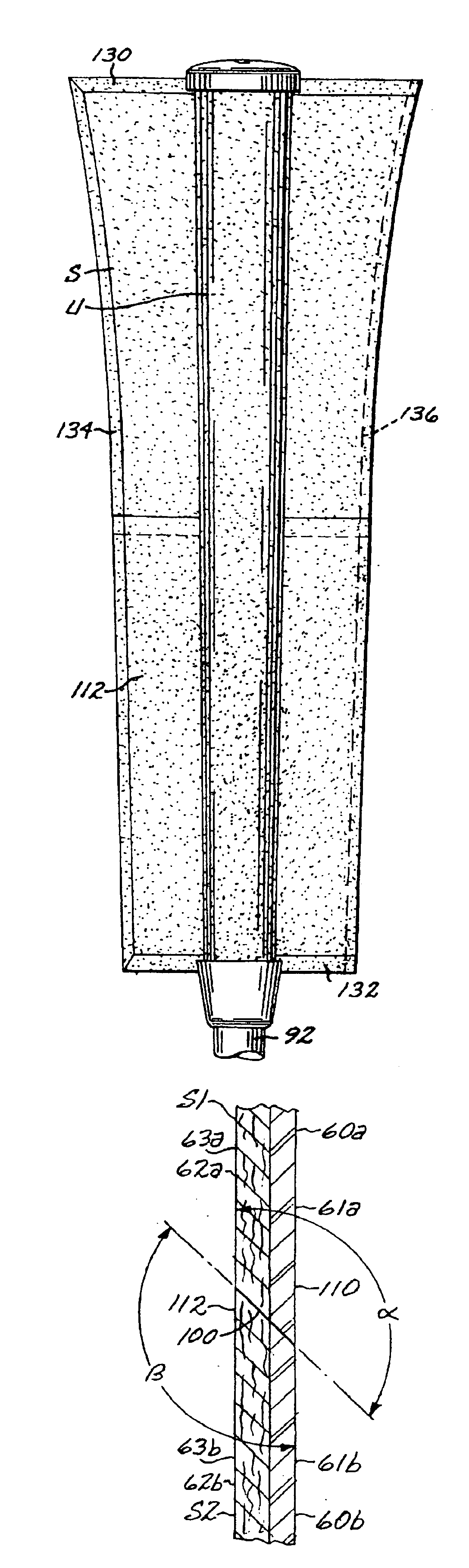
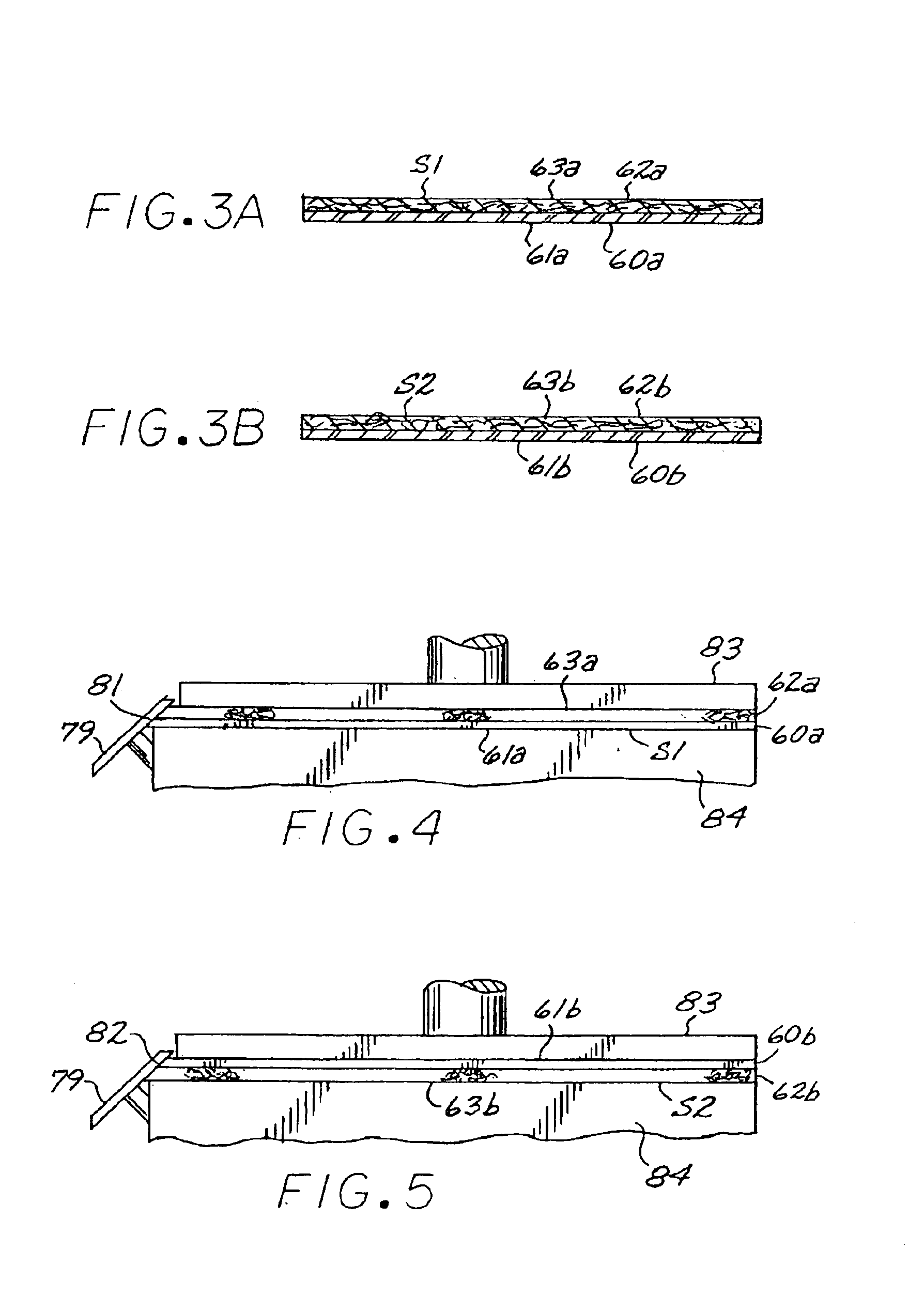
Referring to the drawings, in FIG. 81, a multi-segment single panel grip G embodying the present invention is shown attached to the shaft 55 of a golf club GC. In FIG. 82, a multi-segment single panel putter grip PG is shown attached to the shaft 57 of a putter P. Referring now to the remaining drawings, a preferred form of grip G includes a multi-segment single panel S formed of multiple panels of bonded-together layers of polyurethane 60 and a felt 62 which is then wrapped about and adhered to a resilient underlisting sleeve U of conventional construction. Throughout the application, the term top is used to refer to that which is closest to the butt end of the club opposite the club head, i.e. the end closest to the golfer if that golfer were to be swinging or stroking the club. Similarly, the term bottom is used to define the panel or edge furthest from the butt end of the club.

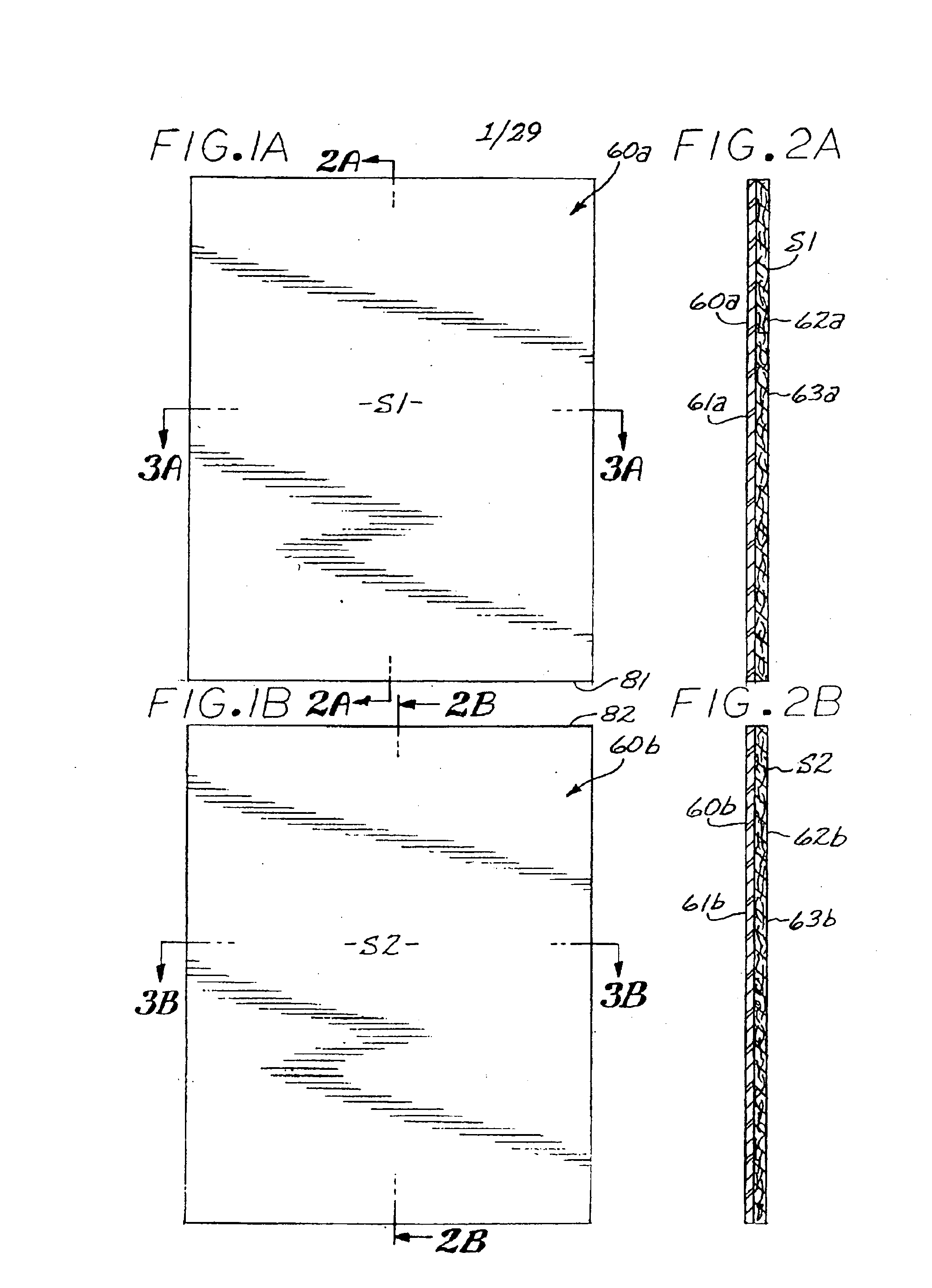
FIG. 1A shows a first two-layer panel S1 with an outside layer 60a and an inside layer 62a (FIG. 2A). F...


PUM

PropertyMeasurementUnit
Angleaaaaaaaaaa
Frictionaaaaaaaaaa
Tackinessaaaaaaaaaa

Abstract

A grip for the handle of a golf club having multiple two layer panels that are wrapped about an underlisting sleeve. The edges of the panels are adhesively sealed together. The grip reduces impact and shock and provides a feeling of tackiness in the manner of a spirally wrapped polyurethane-felt grip while allowing the use of multiple color panels and easy instillation onto a golf club shaft.

Description

BACKGROUND OF THE INVENTION1. Field of the InventionThis application relates to an improved grip for golf clubs.2. Description of the Related ArtApplicant has previously developed resilient grips which successfully reduce impact shock to the muscle and arm joints of the user's of golf clubs and also provide a feeling of tackiness between a player's hands and the grip. See, for example, U.S. Pat. No. 5,797,813 granted to Applicant on Aug. 25, 1998 and U.S. patent Application no. 10 / 392480 filed by Applicant on Mar. 18, 2003.The earliest of these grips utilize a polyurethane-felt strip which is spirally wrapped around an underlisting sleeve that is slipped onto and adhered to a golf club handle. The sides of the strips are formed with overlapping heat depressed recessed reinforcement edges. While such grips have proven satisfactory in reducing impact shock, their fabrication is labor intensive, particularly since the strip must be wrapped manually about the underlisting sleeve within ...

Claims


Application Information

Patent Timeline
IPC IPC(8): A63B53/14A63B59/00B32B27/12B32B27/40E04B2/00
CPCA63B53/14B32B27/40B32B27/12A63B59/0014A63B60/06A63B60/08B32B2553/02B32B3/02B32B5/022A63B60/10
Inventor HUANG, BEN
Owner WINN INC
Learn More