Screw for extruder, bearing segment used in the same and twin screw extruder provided with screw for extruder
a technology of screw and extruder, which is applied in the direction of mixing/kneading with horizontally mounted tools, manufacturing tools, and food shaping, etc., can solve the problems of large kinetic load imposed on both the kneading segment and the rotor segment of the screw body, and achieves the effect of preventing bending, reducing the abrasion of the screw main body and the barrel, and reducing the kinetic load
- Summary
- Abstract
- Description
- Claims
- Application Information
AI Technical Summary
Benefits of technology
Problems solved by technology
Method used
Image
Examples
first embodiment
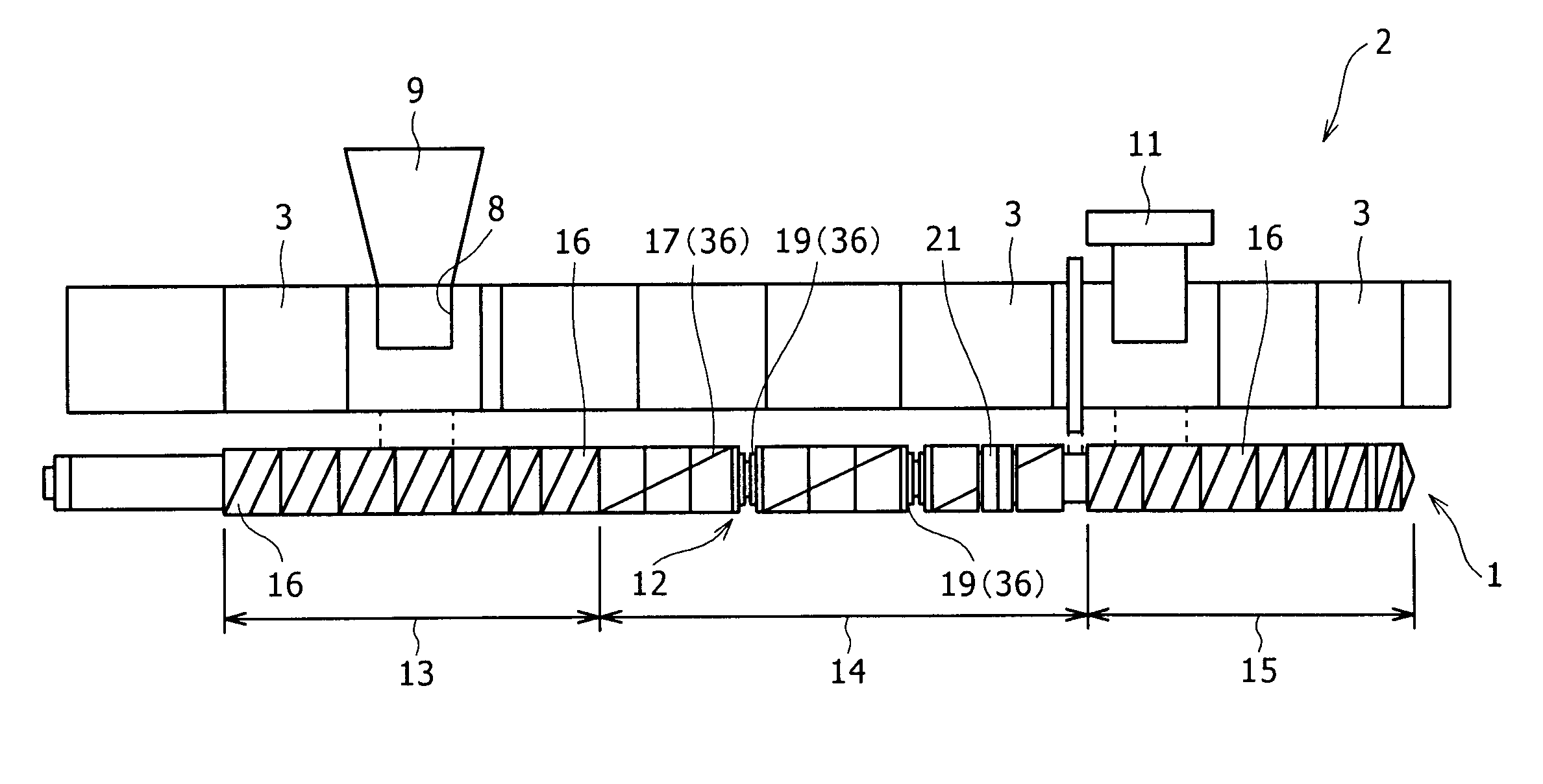
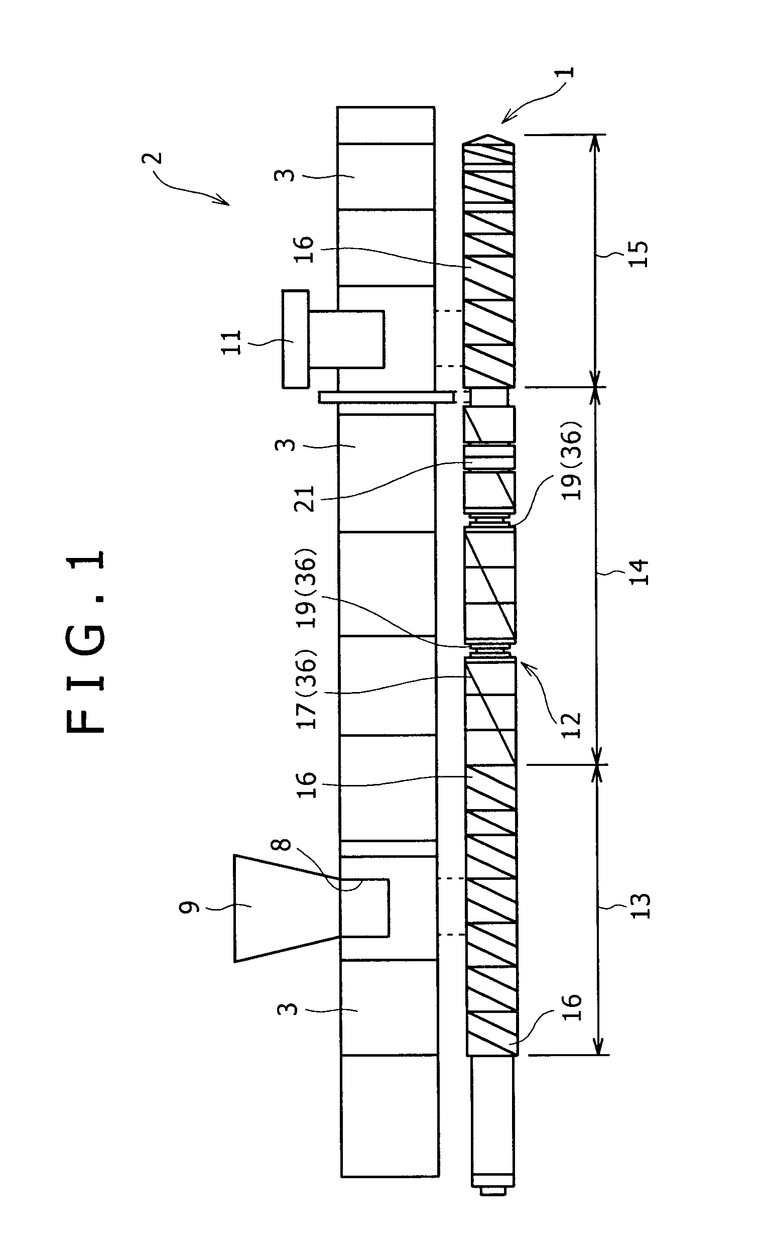
[0068]FIG. 5 schematically shows a conventional screw for extruder 29 having no bearing segment 21 as well as FIG. 1. It should be noted that although the bearing segment 21 is not provided in the conventional screw for extruder 29, except for the above point, the same type of segments are provided in the same combination as in the screw for extruder 1 according to the
[0069]The abrasion amounts of the kneading disk segments 19 provided in A1 and A2 in FIG. 5A are 0.25% or more as shown in a1 and a2 in FIG. 5B. In segments other than A1 and A2 of the kneading portion 14, almost all the abrasion amounts are 0.05% or more. On the other hand, in segments in the feeding portion 13 and segments in the extruding portion 15, the abrasion amounts are low with 0.05% or less. Therefore, it is found that in the conventional screw for extruder 29, abrasion is generated at a position in the axial direction and the abrasion is easily generated particularly in the kneading portion.
[0070]FIG. 6 show...
second embodiment
[0074]FIG. 7A shows the screw for extruder 1 of the In the screw for extruder 1, the bearing segment 21 is provided at a position where a distance S from an end of the downstream of the kneading portion 14 towards the downstream side thereof is 3.0D or less (D: rotational outer diameter of the bearing segment), in the present embodiment, at a position where an end of the downstream of the bearing segment is on the downstream side at a distance of 3.0D from the end of the downstream of the kneading portion 14.
[0075]In the screw for extruder 1 of the second embodiment, although the abrasion amounts of the kneading disk segments 19 shown in a1 and a2 in FIG. 7B are larger than the abrasion amounts of the first embodiment (the abrasion amounts of a1 and a2 in FIG. 6B), the abrasion amounts are smaller than the abrasion amounts of the conventional screw for extruder 29 (the abrasion amounts of a1 and a2 in FIG. 5B). In the abrasion amounts of the kneading disk segments 19 according to t...
third embodiment
[0078]FIG. 8 shows the screw for extruder 1 of the The screw for extruder 1 has a second feeding portion 13b and a second kneading potion 14b following a first feeding portion 13a and a first kneading portion 14a, and the bearing segment 21 is provided at a position corresponding to the first kneading portion 14a.
[0079]In the screw for extruder 1 of the third embodiment, it is confirmed that the abrasion amounts of the kneading disk segments 19 of the first kneading portion 14a and the second kneading potion 14b are smaller than the abrasion amounts of a1 and a2 of the second embodiment. Therefore, as in the screw for extruder 1 of the present embodiment, in the case where a plurality of kneading portions 14 are provided in the axial direction of the screw main body 12 being apart from each other, it is determined as preferable that the bearing segment 21 is at least installed in the first kneading portion 14a located on the most upstream side among the plurality of kneading porti...
PUM
| Property | Measurement | Unit |
|---|---|---|
| angle | aaaaa | aaaaa |
| angle | aaaaa | aaaaa |
| length | aaaaa | aaaaa |
Abstract
Description
Claims
Application Information
 - R&D
- Intellectual Property
- Life Sciences
- Materials
- Tech Scout
- Unparalleled Data Quality
- Higher Quality Content
- 60% Fewer Hallucinations
Browse by: Latest US Patents, China's latest patents, Technical Efficacy Thesaurus, Application Domain, Technology Topic, Popular Technical Reports.
© 2025 PatSnap. All rights reserved.Legal|Privacy policy|Modern Slavery Act Transparency Statement|Sitemap|About US| Contact US: help@patsnap.com


