Large sample low aspect ratio biopsy needle
Active Publication Date: 2010-02-04
CR BARD INC
99 Cites 66 Cited by
AI-Extracted Technical Summary
Problems solved by technology
A biopsy needle must endure significant loads, which makes it difficult to create bio...
Benefits of technology
[0036]According to yet another embodiment, the biopsy device has a generally cylindrical hollow stylet having an axis, and a distal end with a sample recess configured to receive biopsy samples. At least one support fixture holds the stylet, the fixture having at least first and second support portions separated along the axis of the stylet. The stylet has a proximal portion ...
Abstract
A high aspect ratio biopsy needle achieves reliable performance with large solid sample size by means of a variety of features and combinations thereof, including support to prevent bending, reinforcement of the needle, and cutting edges arranged to resist deformation.
Application Domain
Surgical needlesVaccination/ovulation diagnostics
Technology Topic
Aspect ratioBiopsy +2
Image
Examples
- Experimental program(1)
Example
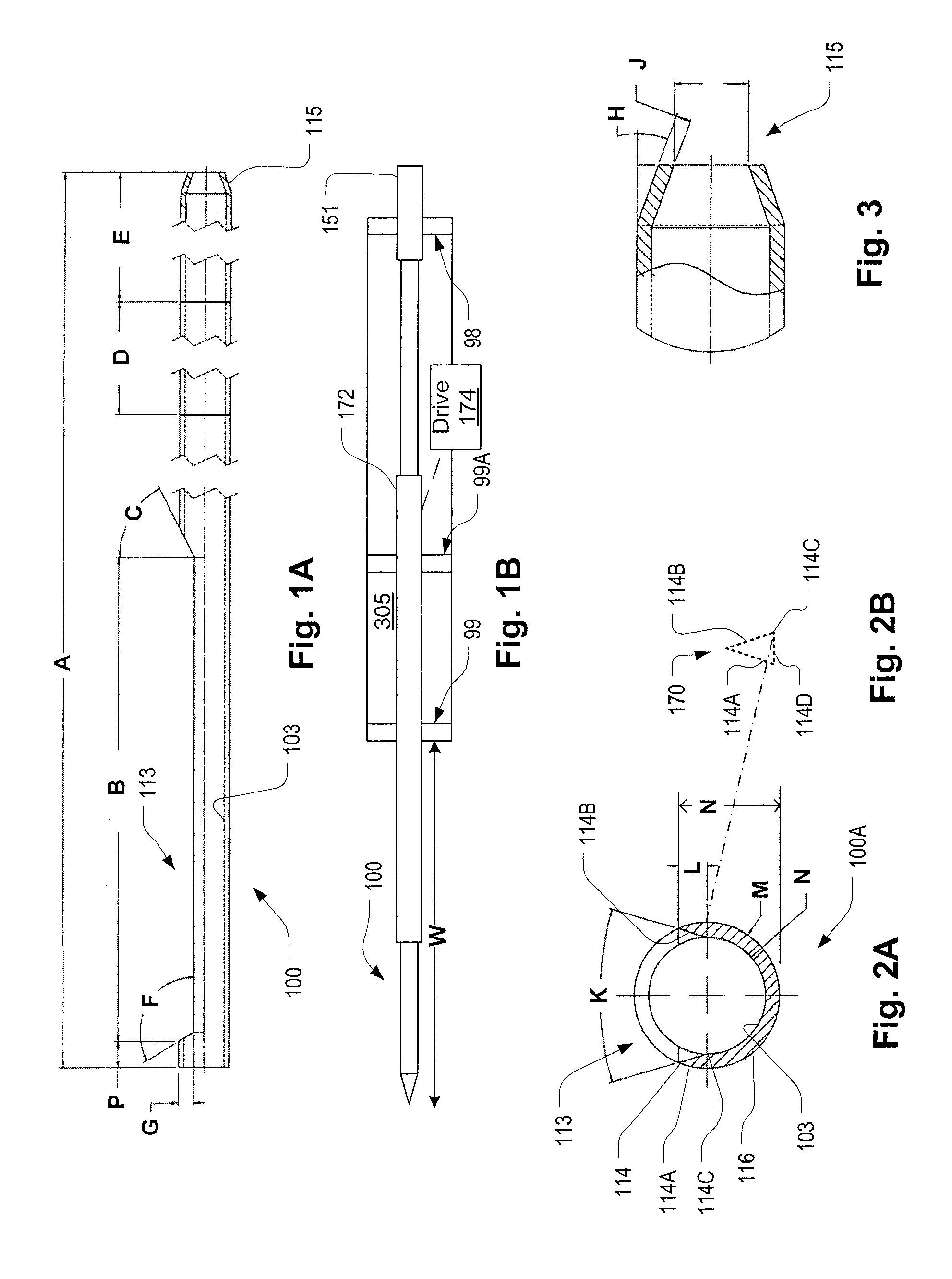
[0057]Various driving mechanisms for biopsy needles are known and many are suitable for use with the invention disclosed below. A preferred type of drive mechanism is a self-contained unit disclosed in U.S. patent Ser. No. 10/500,522, published as U.S. 2005/0203439 (referred to in the background section) filed in the US on Apr. 6, 2005 and U.S. patent Ser. No. 10/500,518, filed in the US on Mar. 1, 2005, both of which are hereby incorporated by reference as if fully set forth herein.
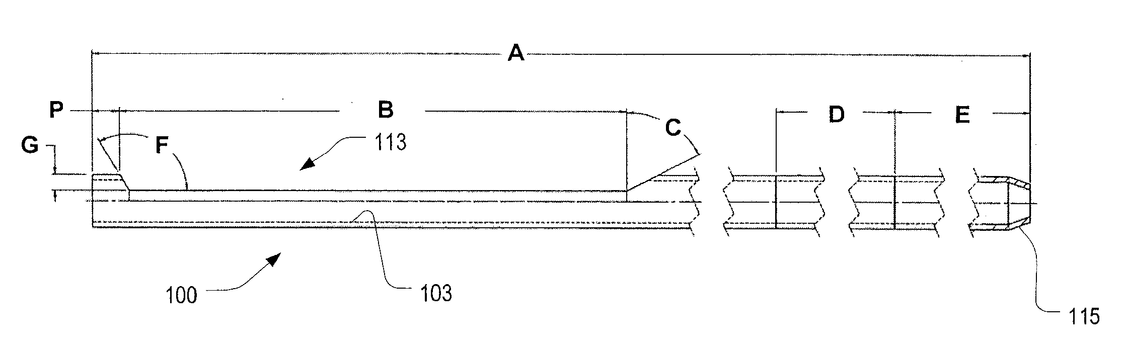
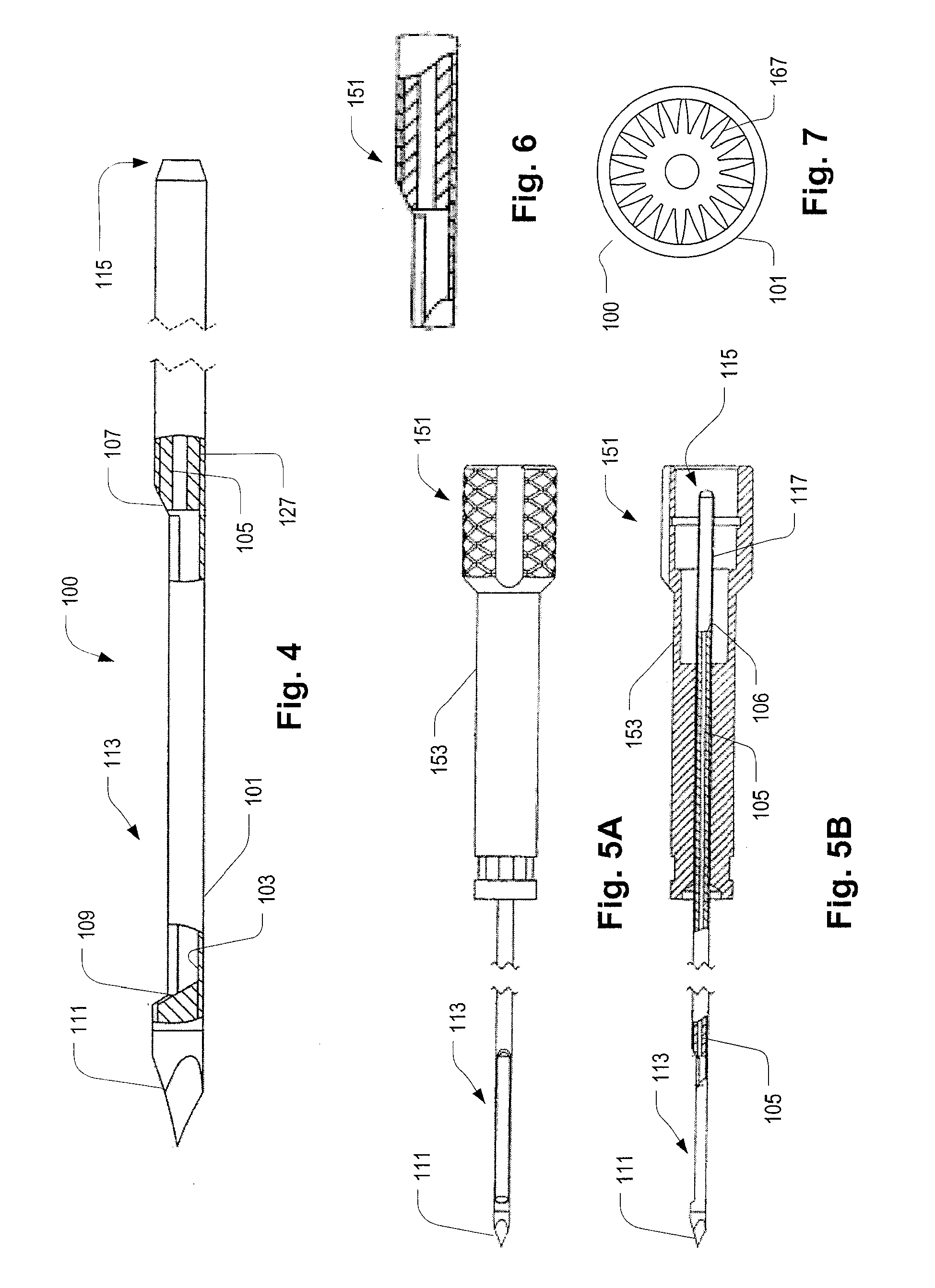
[0058]Referring to FIGS. 1 to 7, a biopsy needle stylet 100 has a sample chamber opening 113 with sloping edges 107 and 109 and sides defined by an internal surface 103 of the stylet 100. The biopsy needle stylet 100 has a fully circular cross-section over most of its length except along the sample chamber opening 113 whose interior surface is indicated at 103. Along the sample chamber opening 113, the stylet 100 has an approximately semicircular cross-section as shown at 100A.
[0059]The edges of the sample chamber opening 113 are chamfered to form cutting edges 114 on either side of the sample chamber opening 113. The outsides 114A of the cutting edges 114 are defined by the cylindrical surface 116 of the stylet 100 whereas the inside surfaces 114B of the cutting edges 114 are defined by flat surfaces, also indicated at 114B. The flat surfaces 114B can be created by machining, for example.
[0060]The ratios and dimensions discussed below and elsewhere in the present application are preferable for a 14 gauge stylet 100, which preferably includes a cutting sheath as described below. Preferably, the sample chamber opening 113 has a width that is between the outer diameter M of the stylet 100 and the inner diameter N of the stylet 100. In addition, preferably, the inside surfaces 114B of the cutting edges 114 slope away from a plane of symmetry 114D such that they are wider apart at the cutting edges 114 than the lines 114C where the inside surfaces 114B of the cutting edges 114 meet the inside surface 103 of the stylet 100.
[0061]Note that the inside surfaces 114B of the cutting edges 114 can be flat or curved to achieve substantially the same configuration. Preferably, the distance between the lines 114C, on opposite sides of the inside surface 103 of the stylet, are separated by a distance approximately equal to the inside diameter N of the stylet. Preferably, the angle K is greater than 10 degrees and more preferably it is greater than 15° and even more preferably, it is about 19 degrees. Preferably the cutting edges 114 have a height L that is between 2.5 and 4 times the wall thickness J (or M−N) of the stylet 100. Preferably, in the embodiments of FIGS. 1-7, the ratio of wall thickness J to outer diameter M is between less than 15 and greater than 4. More preferably the ratio of wall thickness J to outer diameter M is about 10. By providing the angle K and the cutting edges 114 at the heights indicated, the nominal apex angle of the cutting angle can be about 40°, which is a desirable angle for cutting edge 114 integrity and sharpness and also for allowing it to withstand the forces generated by a vacuum which pulls tissue into the sample chamber 313 despite relatively thin walls.
[0062]The cutting edges 114 lie over the centers of the stylet 100 walls and are not aligned with the inner surface 103. That is, it will be observed that each of the cutting edges 114 lies between inner surface 103 and the outer cylindrical surface 116. In this particular example, it will be observed that the sloping side 114B, the surface 114A and the horizontal line intersecting the line 114C form, approximately, a symmetrical triangle 170. Preferably, the cutting edge 114 lies at a radial distance from the longitudinal axis that is less than the inner radius of the basket inner surface 103. In the example, the cutting edge lies well over the base 114D (the base coinciding with a diametric line as in the illustrations) of the triangle 170 so that the angle K is a substantial angle, i.e., is well above zero. As noted, since the walls are thin, and preferably, as discussed below, vacuum levels relatively high, the forces on the cutting edges can be substantial. The forces are compensated by a force with a component directed toward the center of the stylet so the blade edges 114 tend to be pulled together. Thus, providing the cutting edges with the illustrated shape, with the substantial slope ensured by providing a nonzero, positive angle K, helps to supply this compensating force with less risk of bending. Also, the height N of the cutting edges, which is low to help to reduce these forces but not overly so, helps ensure large sample size. In the preferred embodiment, the ratio of the height N to outer diameter of the stylet is about 70% (i.e., N divided by the diameter of inner surface 103 is about 0.7). Another way of stating this is that the plane defined by the two parallel cutting edges cuts the stylet longitudinally at about 70% of its diameter.
[0063]Note that the cutting edge 114 can have multiple angles at the apex and the foregoing is an average at the approach to the apex.
[0064]The ratio of the length B of the sample chamber opening 113 to working length (W, defined, according to convention, as the length of the stylet 100 extending beyond the apparatus used to handle the needle, such as a hand-held driver unitary device—not shown—as disclosed in US Patent Publication No. 20050203439) is in the range of 0.10 to 0.25 and more preferably, the ratio is about 0.1 to 0.2. Preferably, the axial length of the sample recess is between 0.7 and 1 inch and more preferably, about 0.75 inches. Referring in particular to FIG. 1B, a needle, including stylet 100 and cutting sheath 172, is provided with first and second support elements 98 and 99. However, the supports may be parts of a handheld or machine-held biopsy device. The working length W is the portion of the stylet 100 extending beyond the most distal support and outside the housing (not shown in FIG. 1B). As discussed further below, additional bend-resisting support is preferably provided as indicated at 99A.
[0065]In terms of absolute dimensions, the stylet 100 wall thickness J is preferably between 0.005 in. and 0.007 in. and preferably it is about 0.006 in. Preferably the working length is between about 3.5 and 6.5 inches and more preferably, 5.5 inches. This may be varied depending on particular details of the application. For example, for stereotactic applications, the working length is preferably about 140 mm and for handheld applications, the working length can be as low as about 90 mm. Angle C is preferably, between 60 and 65 degrees and 120 degrees and angle F is preferably about 120 degrees. A proximal end 120 of the stylet 100 has a taper forming an angle H of approximately 20 degrees. The total length A of the stylet 100 may be chosen based on the connected driver. In a representative embodiment, the total length A of the stylet 100 is about 10 in.
[0066]Stresses on 14 gauge biopsy needles (the gauge specification being based on the diameter of the stylet 100, not the stylet with an overlying cutting sheath, to be describe further on) are high, due to the small diameter. This can make ensuring the smooth and reliable operation of the needle difficult. For example, a longitudinally-advancing cutting sleeve (See for example, U.S. Pat. No. 7,025,732, hereby incorporated by reference as if fully set forth herein), turning around the stylet 100, may warp the stylet 100 or any bending attending normal manual or machine-held use may cause jamming. Various means of addressing these issues are discussed herein, including preventing bending and reinforcing the stylet, but it has also proved useful to provide a lubricant between the stylet and the cutting sheath. Preferably, such a lubricant is sterile and biocompatible. Many lubricants are known, for example, mineral oil, silicone, or Hyaluronan-based lubricants may be used. Preferably, a lubricant is provided as part of a sterile-prepackaged disposable biopsy needle consumable unit.
[0067]Another preferred mechanism for helping to ensure reliable and smooth operation of a thin needle is to employ a reinforcement in the needle. Preferably this is done without compromising the sample size such as by providing at least one reinforcement element over most of the length of the stylet 100 but not including the sample chamber 113 such that any reinforcement does not reduce the size of the sample chamber 113. In a preferred configuration, the stylet 100 is provided with an insert 127 along a portion of the stylet 100 that is proximal of the sample chamber 113. The insert 127 may take the form of an annular cylindrical tube (also indicated at 127). The insert 127 may be affixed to the stylet 100 with adhesive, by welding, by compression fit, or by nesting. Preferably, the affixation of the reinforcement is affixed at least two points that are separated by a substantial axial distance. Preferably the insert 127 has a relatively narrow tubular lumen 105 or other channel to allow fluids to be conveyed to and from the sample chamber 113, such as air (vacuum) and saline (for flushing samples out of the chamber 113). The distal end of the insert 127 may have a beveled surface 107 that coincides with the chamfered end of the sample chamber 113. Preferably, the insert 127 runs along most of the length of the stylet 100. The insert 127 preferably has an internal diameter of 0.025 or less, at least at the distal end thereof to act as a tissue block, preventing tissue from being drawn into the lumen 105 when the sample chamber is subjected to a vacuum by drawing fluid through the lumen 105.
[0068]A trocar 111 or other type of cutting tip may be proved at the distal end of the stylet. The beveled end 115 of the stylet 100 may be press-fitted into a hub 151. The beveled end 115, so-fitted, may extend into a recess portion 115 of the hub 151 to provide a portion of a connector. For example, the bevel may stretch a flexible annular adapter (not shown) to form a seal. An alternative insert 167 is shown in FIG. 7. The alternative insert 167 may be formed by extrusion, for example, and may be affixed to the stylet 100 wall 101 as discussed above.
[0069]Note that although in the above embodiments, the biopsy needle was described as being used with a cutting sheath that advances and rotates to cut a sample, it is possible to employ a rotating sheath with a blade that is parallel to the sheath axis, or nearly so. FIGS. 8A to 8F illustrate a biopsy needle 201 with an outer sheath 206. Referring to FIG. 8A, the outer sheath 206, in the present embodiment, is cylindrical and has an opening 251 with at least one sharp edge defining a blade 221. A cylinder-shaped inner sheath 236 has a port 231, which, in FIG. 8A, is aligned with the opening 251. The port 231 provides access to a sample chamber 226 which is defined by a volume within the inner sheath 236. A trocar 212 is affixed to a distal end of the inner sheath 236. A handle (not shown) is presumed to be provided, opposite the trocar 212, to support the biopsy needle 200. Note that the sample chamber 226 is not shown with the preferred dimensions as discussed above with reference to FIGS. 2A and 2B but is indicated figuratively here for purposes of discussing the cutting sheath operation.
[0070]FIGS. 8B through 8F show, in section D-D, the needle 201 of FIG. 8A in successive stages of a sampling operation. These stages occur after the needle 201 is inserted into living tissue, a sample of which is to be excised for a biopsy. In FIG. 8B, the outer sheath 206 begins in a position in which it covers the port 231. The needle 201 is inserted while the outer sheath 206 is in this position relative to the inner sheath 236. Once the biopsy needle 201 is in position for sampling, the outer sheath 206 is rotated progressively in a counter-clockwise direction. The counter-clockwise rotation of the outer sheath 206 proceeds progressively through the stages indicated by FIGS. 8B through 8F. The outer sheath 206 may be driven by any suitable drive mechanism.
[0071]While the biopsy needle is in the insertion position shown in FIG. 8B, and after insertion into the tissue to be sampled (not shown), a vacuum is generated in the sample chamber 226 by drawing air through the inner sheath 236. The vacuum may be generated by any suitable device. Once a vacuum has been generated, the outer sheath 206 begins to rotate in the counter-clockwise direction. In FIG. 8C, the opening 251 is shown after having moved partly toward a position of coincidence with the port 231. As the rotation proceeds, the blade 221 advances toward the port 231. In this position, the vacuum, created in the sample chamber 226, draws tissue to be sampled through the opening 251 and port 231 until it begins to enter the sample chamber 226. The outer sheath 206, at this point, moves counter-clockwise toward the position shown in FIG. 8D where the port 231 is fully uncovered, the opening 251 having moved into coincidence with the opening 231. The vacuum causes tissue to be drawn into the sample chamber 226 and the outer sheath 206 continues rotating in the counter-clockwise direction to the position shown in FIG. 8E.
[0072]As the outer sheath 206 rotates toward the position shown in FIG. 8E, the blade 221 partly slices the tissue that has been drawn into the sample chamber 226. As the blade 221 continues toward the position of FIG. 8F, the tissue sample is completely severed from the host and held within the sample chamber 226 while a portion of the outer sheath 206 behind the blade 221 covers the port 231. The biopsy needle 201 can then be withdrawn from the inserted position as it retains the sample.
[0073]To remove the tissue sample, the operation depicted in FIGS. 8B through 8F may be repeated. However, in this case, a positive pressure may be generated in sample chamber 226 before starting the cycle. As the outer sheath 206 rotates clockwise through the successive positions starting with the one shown in FIG. 8F, a pressure is applied to the sample chamber 226 and the port 231 is uncovered. This causes the pressure in sample chamber 226 to force the tissue sample out through the uncovered port (about the position shown in FIG. 8D). The cycle may then continue to the point shown in FIG. 8B.
[0074]As in the previous embodiments, the outer sheath 206 could rotate in either direction, or both directions, in alternative embodiments. For example, the port 231 could be uncovered by rotating in one direction and the cutting operation and covering could occur after reversing the direction of rotation immediately after uncovering the port 231. This alternative may be provided for all of the embodiments described herein. In addition, the blade 221 may be on either or both sides of the opening 251. As in the previous embodiments, the speed of rotation of the outer sheath 206 may be constant or variable. For example, to reduce amplify torque from the drive mechanism, a reduced force/torque transmission ratio of the drive may be provided to level the prime mover load through the cutting phase. The port 231 may be angled to help reduce the instantaneous torque load on the outer sheath 206 drive mechanism (not shown).
[0075]The other type of cutting sheath discussed above is illustrated in FIGS. 1B and 9. The stylet 100 lies within the cutting sheath 301 and both are held in a frame 305. The stylet 100 extends all the way to the hub 151 which is held in a single longitudinal position relative to the frame 305, thereby preventing the stylet 100 from moving axially. The cutting sheath 301 simultaneously rotates and advances and retracts relative to the frame 305 when a gear 307 is correspondingly driven rotationally by a drive, which is shown figuratively at 174 in FIG. 1B. The gear 307 is attached to the cutting sheath 301 and a threaded cylinder 309 in mesh with a nut 311 affixed to the frame 305. Thus, the rotation of the gear 307 causes axial translation of the cutting sheath 301 as well as rotation thereof. The device shown in FIG. 9 may form part of a disposable unit that fits into a reusable drive.
[0076]Referring to FIG. 10, a biopsy needle stylet 400 is similar to the biopsy needle stylet of FIG. 4, having a sample chamber opening 413 with sloping edges 407 and 409 and an interior 403 formed from a cylindrical element 401. The proximal part 427 of the cylindrical element 401 receives an extension 408 of a heavy stylet portion 428. The thick-walled heavy stylet portion 428 provides an element which is substantially stiffer than a cylinder whose wall thickness and diameter is the same as that coinciding with the sample recess 412 such that this embodiment may avoid the need for an additional reinforcement. Other features are similar to the embodiment of FIG. 4. Referring to FIG. 11, in a further variation, the reinforcement is obtained in a main portion of the stylet 403 by means of a composite reinforcement element such as a carbon fiber wind layer 422. Here, the element 425 may be thinner-walled than in previous embodiments due to the additional stiffness provided by the composite support 422.
[0077]The internal reinforcement elements described in the foregoing can have various cross-sectional shapes, for example a cross-shape as indicated at 434, which may provide vacuum-transmitting lumens at the corners 432 or may include a central lumen 431 for that purpose. Other shapes such as triangular, square, pentagonal or lobed structures may be employed, again, with our without a centrally-located lumen.
[0078]The issue of rigidity is also preferably addressed by means of a-constraining support structure that helps to prevent the bending of the stylet. FIGS. 13A and 13B show stylet 443 with a working portion B and a supported portion proximal (remainder of the stylet 443 to the left in the drawings) thereof. Typically needles have a substantial length in the proximal part, which extends well into the body of the support, and control apparatus with which it interoperates. Support for the needle is typically provided by holding the needle at it rear end where it engages a support apparatus. For example, many biopsy needles have a needle shooting mode in which the needle is driven into, or adjacent, the tissue mass to be sampled by a spring or other paroxysmal actuator. So the proximal terminal end of the needle would ordinarily be held by such a component, which is illustrated figuratively as the support points 448 and 454 in both of FIGS. 13A and 13B. The distal support is indicated at 442 in FIG. 13A in a typical configuration. Support of the stylet 443 may be provided by a part of a permanent reusable structure, a part of a disposable, limited use structure, or a combination of the permanent reusable structure and the disposable structure. For example, see U.S. application Ser. Nos. 10/500,522 and 10/500,518 incorporated by reference above which show that the needle is carried by a plastic carrier that accompanies the non-reusable unit.
[0079]Preferably, additional or modified supports are provided as discussed below. Both embodiments of FIGS. 13A and 13B have a cutting sheath 444 driven by a drive 490, which can be either rotational or axial or both as discussed above and in the documents incorporated by reference. The cutting sheath tightly encloses the stylet 443 so that support of the cutting sheath 444 provides support of the stylet 443 therewithin. In the present embodiment, additional support is provided by the supports 450, which are approximately equidistant between supports 442 and 448. Additional supports or alternative locations for the additional support are indicated at 452. The result of the additional support is to constrain the ability of the stylet 443 and sheath 444 combination to bend.
[0080]The most effective location for the additional supports 450 is midway between the supports 440 and 448 but this may or may not be possible given other packaging requirements, depending on the particulars of the application. A compromise on the position of additional supports may therefore be required. Additional supports 452 and the strength and rigidity provided by the supports may be combined to aid in preventing bending. In addition or alternatively, as illustrated in embodiment of FIG. 13B, an elongate support 446 may be provided to constrain the bending of the stylet 443 and sheath 444 combination. The supports may be provided in the design of the biopsy needle in a variety of fashions. They may include collars, recesses in fixed bulkheads, protrusions in the housing, or any functional element that constrains movement and bending of the stylet 443 and sheath 444 combination. It has been found that for smaller diameter needles, such as a 14 gauge needle, that the additional constraint of the needle is important compensation for the thinness of the needle and has resulted in higher operational reliability than when the support is provided without significantly constraining bending. Preferably, at least a multiple of the supports 448, 452, 450, 442, or a major fraction of support 446 should coincide with the longitudinal extent of the reinforcement or nearly so, so that the fixity of the supports is transmitted through the reinforcement's rigidity, to the stylet.
[0081]To assist in securing large sample size, the magnitude of the vacuum used to draw samples into the sample chamber is preferably at least 21 in. Hg and more preferably at least 22 in. Hg.
[0082]While the present invention has been disclosed with reference to certain preferred exemplary embodiments, numerous modifications, alterations, and changes to the described exemplary embodiments are possible without departing from the sphere and scope of the present invention. Accordingly, it is intended that the present invention not be limited to the described exemplary embodiments, but that it have the full scope of the following claims and the equivalents thereof.
PUM


Description & Claims & Application Information
We can also present the details of the Description, Claims and Application information to help users get a comprehensive understanding of the technical details of the patent, such as background art, summary of invention, brief description of drawings, description of embodiments, and other original content. On the other hand, users can also determine the specific scope of protection of the technology through the list of claims; as well as understand the changes in the life cycle of the technology with the presentation of the patent timeline. Login to view more.
Similar technology patents
Flexible display panel
ActiveUS20140098471A1prevent bendingreduce dead space
Owner:SAMSUNG DISPLAY CO LTD
Classification and recommendation of technical efficacy words
- prevent bending
Flexible display panel
ActiveUS20140098471A1prevent bendingreduce dead space
Owner:SAMSUNG DISPLAY CO LTD