Optical communication wire limiting equipment

A technology of optical communication and wires, which is applied in the field of optical communication wires. It can solve problems such as affecting communication work, difficulty in re-joining optical fibers, and inability to stably clamp and fix optical fiber cables to achieve the effect of improving stability and facilitating stable installation.

Active Publication Date: 2020-04-14
广州卫讯科技有限公司
View PDF10 Cites 0 Cited by
  • Summary
  • Abstract
  • Description
  • Claims
  • Application Information

AI Technical Summary

Problems solved by technology

[0005] The object of the present invention is to provide a limiting device for optical communication wires, so as to solve the above-mentioned background technology in the routing of overhead open wires, if the optical fiber is bent too violently or bumped and pressed, it may still be broken. Dangerous, and because the connection between the two ends of the optical fiber requires very precise alignment, it is difficult to rejoin the broken optical fiber, and it cannot be stably clamped and fixed according to the specific diameter of the optical fiber cable, resulting in the easy detachment of the optical fiber cable In the case of falling, it is extremely easy to cause harm to pedestrians, and it is also easy to cause damage to the cable itself, which affects the normal communication work.

Method used


Image

  • Optical communication wire limiting equipment
  • Optical communication wire limiting equipment
  • Optical communication wire limiting equipment

Examples


Embodiment Construction

[0025] The following will clearly and completely describe the technical solutions in the embodiments of the present invention with reference to the accompanying drawings in the embodiments of the present invention. Obviously, the described embodiments are only some, not all, embodiments of the present invention. Based on the embodiments of the present invention, all other embodiments obtained by persons of ordinary skill in the art without making creative efforts belong to the protection scope of the present invention.

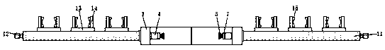
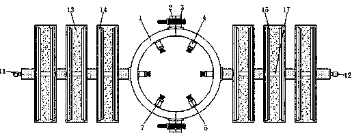
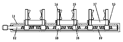
[0026] see Figure 1-6 , the present invention provides a technical solution: a positioning device for optical communication wires, including an installation support ring 1, fastening bolts 3, a support cross bar 11 and a clamping plate 14, and a mounting plate is fixedly installed on the outside of the installation support ring 1 2, and fastening bolts 3 are installed through the mounting plate 2, and the inner side of the installation support ring 1 is fixed...


PUM


Abstract

The invention discloses optical communication wire limiting equipment comprising mounting supporting rings, fastening bolts, supporting cross rods and clamping plates. Mounting plates are fixedly mounted on the outer sides of the mounting support rings; the fastening bolts are mounted on the mounting plates in a communicating manner; limiting sleeve rods are fixedly mounted on the inner sides of the mounting support rings; limiting ejector rods are arranged on the inner sides of the limiting sleeve rods; the limiting ejector rods are connected with the mounting support rings through the limiting sleeve rods; the limiting ejector rods are arranged on the inner sides of storage grooves. And the storage grooves are formed in the limiting sleeve rods, transverse grooves are formed in bearing plates, vertical rods are connected with the bearing plates through the transverse grooves, driving rings and adjusting rods are both arranged on the inner sides of adjusting grooves, the adjusting grooves are formed in the supporting cross rods, and the adjusting rods are connected with the supporting cross rods through the adjusting grooves. According to the optical communication wire limiting equipment, the suspension point of the cable can be supported stably; and the excessive bending of the optical fiber in the limiting and supporting process of the optical fiber cable can be avoided, sothat the normal communication work is protected from being affected by the breakage of the optical fiber.

Description

technical field [0001] The invention relates to the technical field of optical communication wires, in particular to a positioning device for optical communication wires. Background technique [0002] Optical communication wires, or fiber optic cables, consist of a core, cladding, and outer protective covering. The core and the fiber shell with a high refractive index are usually made of high-quality silica glass, but now there are also optical fibers that use plastic as the material. The optical fiber wiring generally adopts underground buried lines and overhead open lines. One is buried underground, and the other is One is to use electric poles for high-altitude routing. The existing fiber cables often have the following problems in the routing process: [0003] 1. In the wiring method of overhead open wire, if the optical fiber is bent too violently or hit and pressed, there is still a danger of breaking, and because the connection between the two ends of the optical fib...

Claims


Application Information

Patent Timeline
Patent Type & Authority Applications(China)
IPC IPC(8): G02B6/46G02B6/48
CPCG02B6/46G02B6/48G02B6/483
Inventor 不公告发明人
Owner 广州卫讯科技有限公司
Why Eureka
Try Eureka