Display device and backlight module

Inactive Publication Date: 2013-10-03
TCL CHINA STAR OPTOELECTRONICS TECH CO LTD
View PDF6 Cites 0 Cited by
  • Summary
  • Abstract
  • Description
  • Claims
  • Application Information

AI Technical Summary

Benefits of technology

[0022]The advantages of the present invention is that as compared to the existing prior art, the display device and the backlight module can effectively prevent the warpage or bending of the waveguide in

Problems solved by technology

As a result, the waveguide will not be properly supported at the area adjacent to its inlet area.
This warpage and ben

Method used


Image

  • Display device and backlight module
  • Display device and backlight module
  • Display device and backlight module

Examples


Embodiment Construction

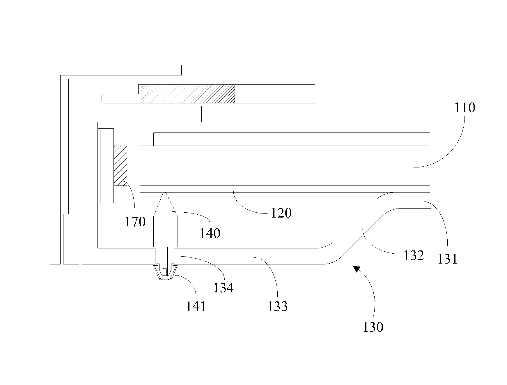
[0028]Referring to FIG. 1, a first embodiment of a backlight module is provided. The backlight module comprises a waveguide 110, a reflector 120, a backframe 130, a shimming device 140 and a slight source 170.

[0029]The reflector 120 arranged behind the waveguide 110. The backframe 130 carries and supports the waveguide 110 and the reflector 120. The supporting frame 130 includes a carrier 131, a curve portion 132 and a recess 133. The carrier 131 holds firmly the waveguide 110 and the reflector 120. In the curve area 132 of the waveguide 110 adjacent to the light source 170, an extension is formed and extends away from the waveguide 110. After a preset distance, the extension is in parallel to the carrier 131 and therefore defines a recess 133. As a result, the waveguide 110 and the backframe 130 is defined with a gap adjacent to the light source 170 in an area of light inlet area. The shimming device 140 is disposed within the gap so as to effectively support the waveguide 110 and ...


PUM


Abstract

The present invention discloses a display device and a backlight module. The backlight module comprises a waveguide, a reflector, a backframe and a shimming device. The reflector arranged behind the waveguide. The backframe carries and supports the waveguide and the reflector. An light inlet edge of the waveguide and the backframe is defined with a gap in which a shimming device is seated within the gap so as to effectively support the waveguide. This arrangement can effectively prevent the warpage or bending of the waveguide in the area of the light inlet area. Stabilizing the efficiency of illumination of the backlight module. As a result, the insufficient of illumination of the waveguide encountered by the prior art is avoided.

Description

FIELD OF THE INVENTION[0001]The present invention relates to a technology of display device, and more particularly to a displaying device and its backlight module.BACKGROUND OF THE INVENTION[0002]In the field of edge-type backlight module powered by LED, in order to make the backlight module slim and compact, the waveguide has become thinner and thinner. Currently, the thickness of the waveguide has reached to 2.00 mm. It is estimated that a waveguide of thickness of 1.5 mm or even 1.0 mm is expected in near future. According to the field requirements, the frame used to support and carries the waveguide will be distant to the waveguide in an area adjacent to the inlet of the light source. As a result, the waveguide will not be properly supported at the area adjacent to its inlet area. This arrangement will create a gap between the inlet of the waveguide and the frame. As the waveguide becomes thinner and thinner, the rigidity of the waveguide itself reduces as well. Accordingly, the...

Claims


Application Information

Patent Timeline
IPC IPC(8): G09F13/04
CPCG02F1/133608G02B6/0055G02B6/0088
Inventor LI, QUAN
Owner TCL CHINA STAR OPTOELECTRONICS TECH CO LTD
Why Eureka
Try Eureka