Method for producing ceramic-honeycomb-structure-molding die and method for producing ceramic honeycomb structure

a technology of structure and die, which is applied in the field of method for producing ceramic honeycomb structure, can solve the problems of deteriorating precision of width and depth of groove, affecting the use of tools, so as to prevent the breakage and warpage of rotating tools

Active Publication Date: 2010-02-25
HITACHI METALS LTD
View PDF4 Cites 4 Cited by
  • Summary
  • Abstract
  • Description
  • Claims
  • Application Information

AI Technical Summary

Benefits of technology

[0011]Accordingly, an object of the present invention is to provide a method for producing a molding die while preventing the breakage and warpage of a rotating tool during forming grooves, so that the grooves do not suffer scratching and partial width expansion, and a method for producing a honeycomb structure without deformation and breakage.

Problems solved by technology

When a narrow, deep grooves 20 are formed by a rotating thin tool 40, the tool 40 is likely deformed or warped by large machining resistance in a thickness direction, resulting in meandering grooves and damaging of the tool 40.
The chatter vibration deteriorates the precision of width and depth of the grooves 20, and damages the tool 40.
Although the method of JP 11-70510 A is effective to some extent to prevent the meandering of grooves and damage to the tool, a sufficient effect cannot be obtained particularly when the tool has a reduced cutting performance due to wear, failing to solve these problems completely.
As a result, the tool is likely broken during machining, its fragments scratching grooves, and when the tool is warped if not broken the groove width partially expands, causing irreparable damage.
If the die had scratch or partially enlarged width in a groove even at only one point, an extrusion-molded honeycomb structure would suffer defects such as deformation, breakage, etc. in its cell walls, making the die unusable.
The above problems make the production cost of a molding die higher, posing a large obstacle to the reduction of the production cost of a honeycomb structure.

Method used


Image

  • Method for producing ceramic-honeycomb-structure-molding die and method for producing ceramic honeycomb structure
  • Method for producing ceramic-honeycomb-structure-molding die and method for producing ceramic honeycomb structure
  • Method for producing ceramic-honeycomb-structure-molding die and method for producing ceramic honeycomb structure

Examples


example 1

[0033](1) Formation of Moldable-Material-Supplying Apertures

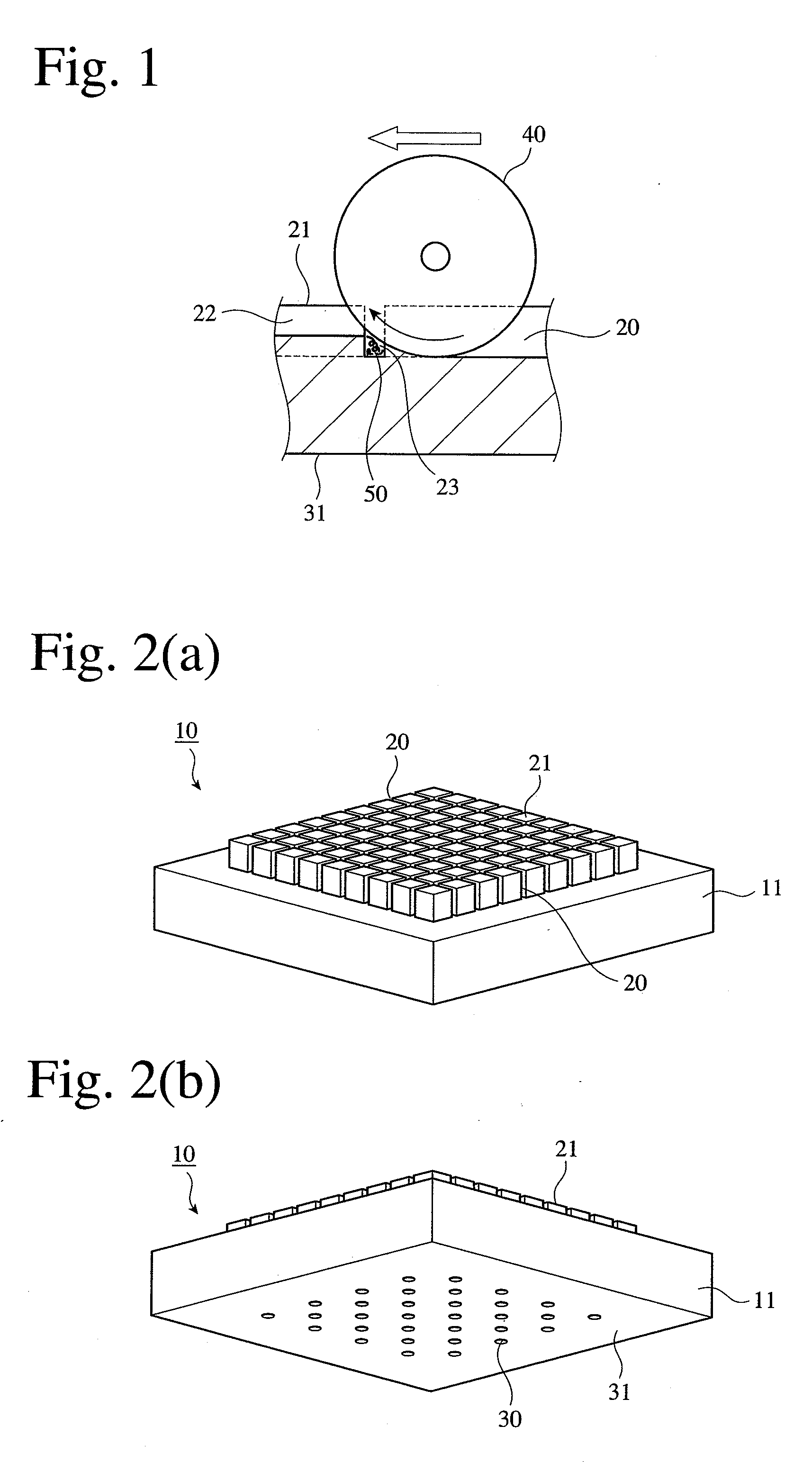
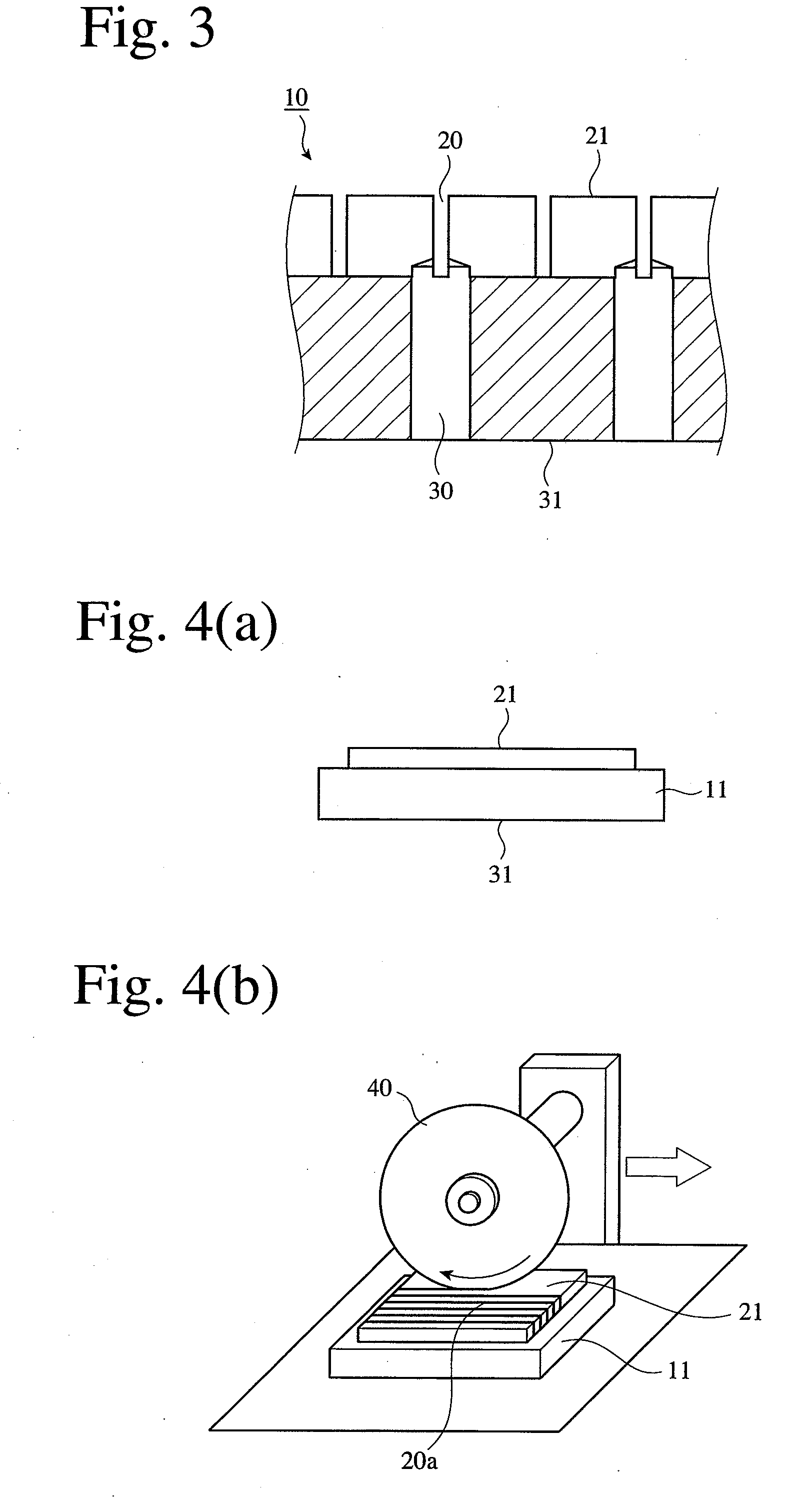
[0034]Prepared was a die-forming work 11 made of alloy tool steel (JIS G4404), which had a projected groove-having surface 21 of 240 mm×240 mm, and a surface 31 of 260 mm×260 mm from which apertures were formed, as shown in FIG. 4(a). The die-forming work 11 was drilled with a cemented carbide drill having a diameter of 1.1 mm and a tip angle of 140° from the aperture-machining surface 31 to form apertures 30 as shown in FIG. 3.

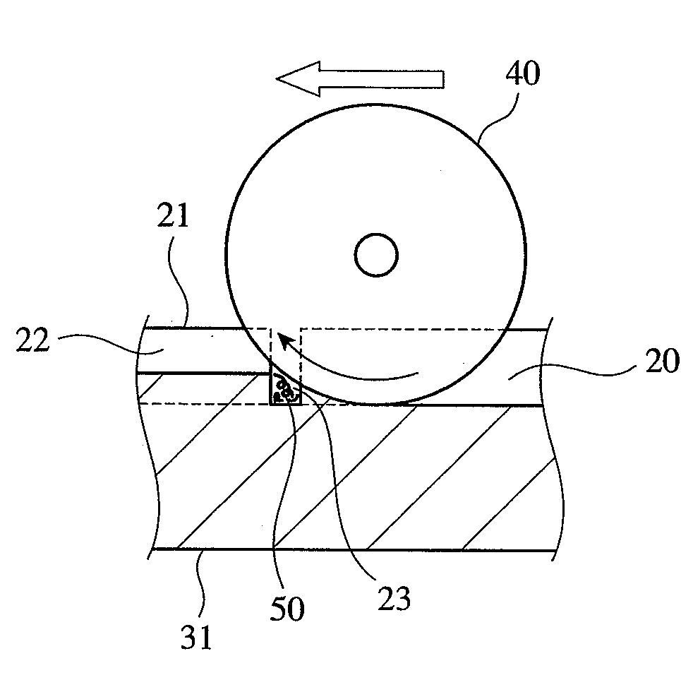
[0035](2) Formation of First Grooves

[0036]The groove-having surface 21 was machined by a rotating tool 40 to form grooves 20. The tool 40 was a thin grinder disc having a thickness of 0.25 mm and a diameter of 100 mm. First, parallel grooves 20 as deep as 4 mm were formed by down-cutting (first pass). The second-pass machining was then conducted by up-cutting, such that the previously machined grooves 20 became 2.5 mm deeper, namely the depth of the machined grooves 20 became 6.5 mm. The diameter of ...


PUM

PropertyMeasurementUnit
thicknessaaaaaaaaaa
diameteraaaaaaaaaa
cutting depthaaaaaaaaaa

Abstract

A method for producing a die for molding a ceramic honeycomb structure, which has molding grooves arranged in a lattice pattern and apertures communicating with the molding grooves for supplying a moldable material, wherein the formation of the lattice-patterned grooves by machining is conducted by a first machining operation for forming pluralities of first parallel grooves, and a second machining operation for forming second grooves crossing the first grooves; wherein the first and second machining operations are conducted by at least 2 passes of grinding or cutting using a rotating tool; and wherein the second machining operation is conducted by up-cutting in the second pass or later, and a method for producing a ceramic honeycomb structure using such a die.

Description

FIELD OF THE INVENTION[0001]The present invention relates to a method for producing a die used for the extrusion molding of a ceramic honeycomb structure, and a method for producing a ceramic honeycomb structure.BACKGROUND OF THE INVENTION[0002]A ceramic honeycomb structure (simply called “honeycomb structure” below) used as a filter for cleaning an exhaust gas, etc. is produced by extruding a moldable ceramic material through a honeycomb-structure-molding die (simply called “molding die”) to form a honeycomb molding, and drying and sintering it. As shown in FIGS. 2(a) and 2(b), the molding die 10 is formed from a die-forming work 11 having such a shape that a groove-having surface 21 projects, that moldable-material-supplying apertures 30 are formed in the die-forming work 11 such that they extend from an aperture-having surface 31, and that lattice-patterned grooves 20 are formed on a groove-having surface 21. As shown in FIG. 3, the moldable-material-supplying apertures 30 of the...

Claims


Application Information

Patent Timeline
Patent Type & Authority Applications(United States)
IPC IPC(8): B29C47/00B26D3/00
CPCB23P15/243B28B2003/203B24B19/02Y10T83/0524
Inventor KURAKAKE, KAZUYUKIOGATA, TOMOHISAINOUE, HIROSHI
Owner HITACHI METALS LTD
Why Eureka
Try Eureka