Light guide plate and a planar lighting device using the same

Inactive Publication Date: 2007-06-28
FUJIFILM CORP
View PDF3 Cites 4 Cited by
  • Summary
  • Abstract
  • Description
  • Claims
  • Application Information

AI Technical Summary

Benefits of technology

[0020] The light guide plate according to the first aspect of the present invention can suppress the warpage that may be caused by the heat generated from the linear light sources fitted in the grooves in the back surface. Hence, planar illuminating light that is uniform and substantially free from unevenness in brightness can be emitted from the light exit surface.

Problems solved by technology

As a result, the two surfaces of the light guide plate thermally expand in different amounts and an internal stress is created in the light guide plate, causing it to become warped.
The wa

Method used


Image

  • Light guide plate and a planar lighting device using the same
  • Light guide plate and a planar lighting device using the same
  • Light guide plate and a planar lighting device using the same

Examples


Example

[0039] Hereinafter, the light guide plate according to the present invention and the planar lighting device using the same will be described in detail based on the preferred embodiments shown in the accompanying drawings.

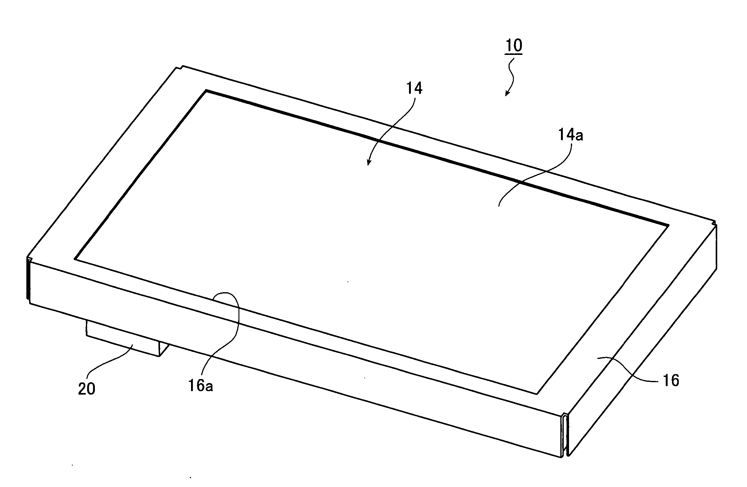
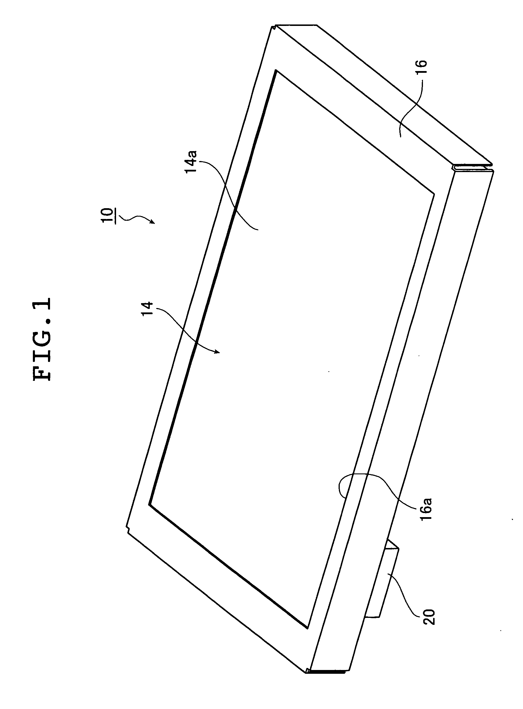
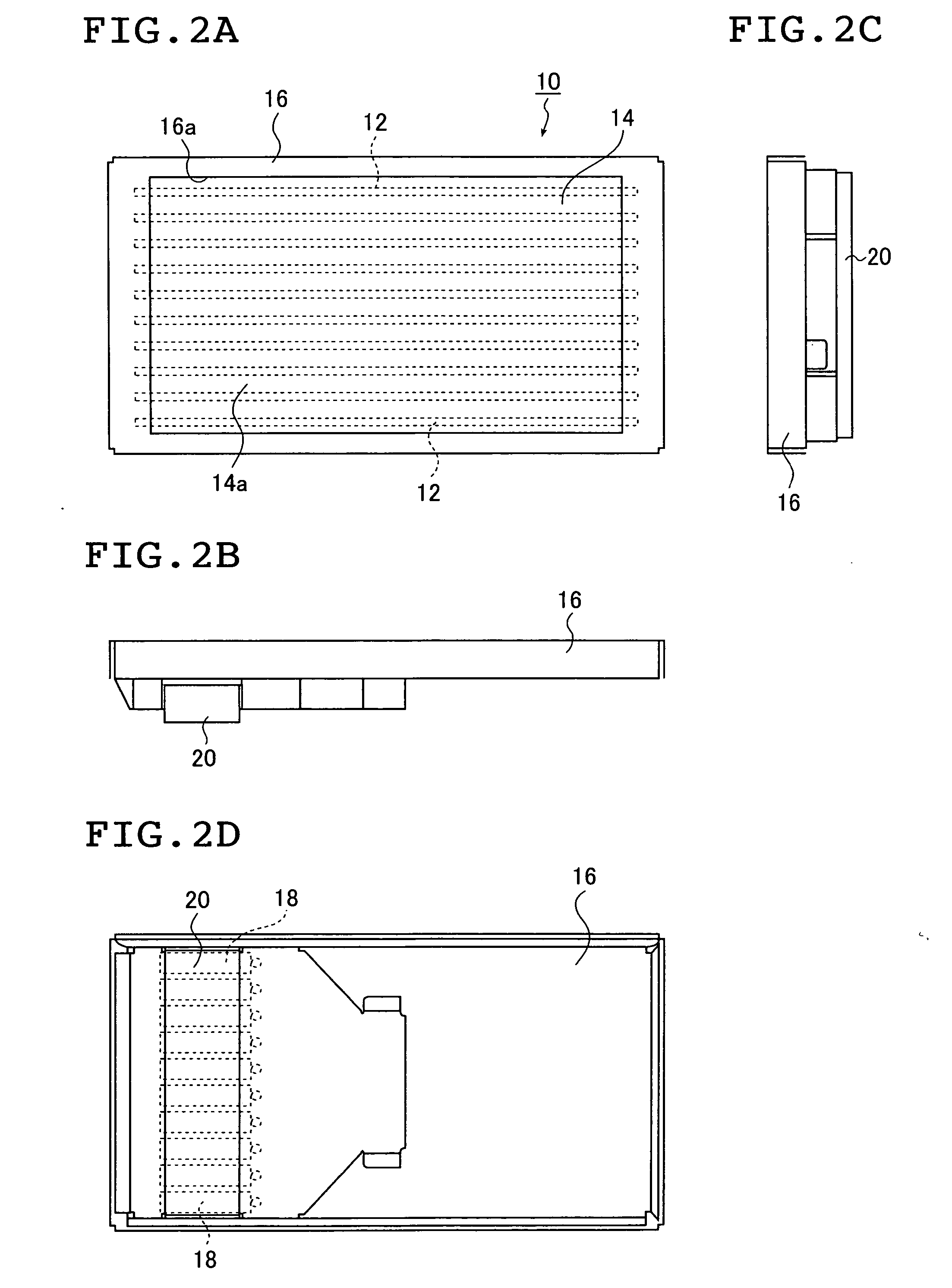
[0040]FIG. 1 is a schematic perspective view of an embodiment of the planar lighting device of the present invention as it is seen from the light exit surface. FIGS. 2A, 2B, 2C and 2D are a front view, a longitudinal side view, a transverse side view, and a rear view, respectively, of the planar lighting device shown in FIG. 1. FIG. 3 is a partial section of an embodiment of the planar lighting device shown in FIG. 1. Note that these and other figures that follow are shown enlarged in the direction of thickness of the planar lighting device in order to provide better understanding.

[0041] As shown in FIGS. 1 and 2A-2D, the planar lighting device generally indicated by 10 comprises a main body 14 that includes a plurality of linear light sources 12 and which emits u...


PUM


Abstract

A light guide plate of the invention has a plurality of unit light guide plates that are formed of a transparent resin material and which are joined together. Each of the unit light guide plates has a flat rectangular light exit surface and a back surface that is opposite the light exit surface and which has a parallel groove formed in generally a center and parallel to a side of the rectangular light exit surface. The light guide plate is used with a linear light source fitted in the parallel groove, satisfying the inequality (L0/280)2·k(14T2+710T)·(−0.65 log S+1.9)≦10, where L0 is the length (mm) of the light guide plate, k is the linear expansion coefficient [/° C.] of the resin material, Ts is the surface temperature [° C.] of the linear light source that has become stable, S is half of the cross-sectional area [mm2] of the unit light guide plate as it is cut through a plane perpendicular to the parallel groove, and T=Ts−25.

Description

[0001] The entire contents of the documents cited in this specification are incorporated herein by reference. BACKGROUND OF THE INVENTION [0002] The present invention relates to a transparent light guide plate that diffuses light from a linear light source in a direction of plane so that uniform illuminating light emerges from a light exit surface, as well as a planar lighting device using the same. [0003] A liquid crystal display device is provided with a backlight unit for irradiating a liquid crystal panel (LCD) with light from its rear side and illuminating the liquid crystal panel. A known backlight unit is one that uses a flat plate of transparent resin as a light guide plate for converting light from a light source into planar light. The backlight unit using such light guide plate usually comprises an illuminating light source, a light guide plate that diffuses light emitted from the light source to irradiate the liquid crystal panel, a prism sheet or diffusion sheet for caus...

Claims


Application Information

Patent Timeline
IPC IPC(8): G02B6/10
CPCG02B6/0021G02B6/0046G02B6/0053G02B6/0088
Inventor MATSUSHITA, MOTOHIKO
Owner FUJIFILM CORP
Why Eureka
Try Eureka