Glass sheet
- Summary
- Abstract
- Description
- Claims
- Application Information
AI Technical Summary
Benefits of technology
Problems solved by technology
Method used
Image
Examples
examples
[0189]Working examples of the present invention are described specifically below, but the present invention is not limited thereto.
(Composition of Glass Sheet)
[0190]In this test example, a float glass was manufactured using a glass sheet of a glass material A having the following composition.
(Glass Material A)
[0191]A glass containing, as represented by mass %, 68.5% of SiO2, 5.0% of Al2O3, 14.7% of Na2O, 0.2% of K2O, 4.1% of MgO, and 7.2% of CaO.
[0192]Glass transition temperature (Tg): 556° C.
(Na2O Concentration)
[0193]The Na2O concentration was measured by the above-described XRF (X-ray Fluorescence Spectrometry) method. The quantitative determination was performed by a calibration method using an Na2O standard sample. Based on the measurement results, the above-described ΔNa2O was determined.
(Average 1H / 30Si Count, Fluorine Concentration)
[0194]The fluorine concentration and 1H / 30Si count distributions in the thickness direction were measured using the above-described secondary ion ...
examples 1 to 4
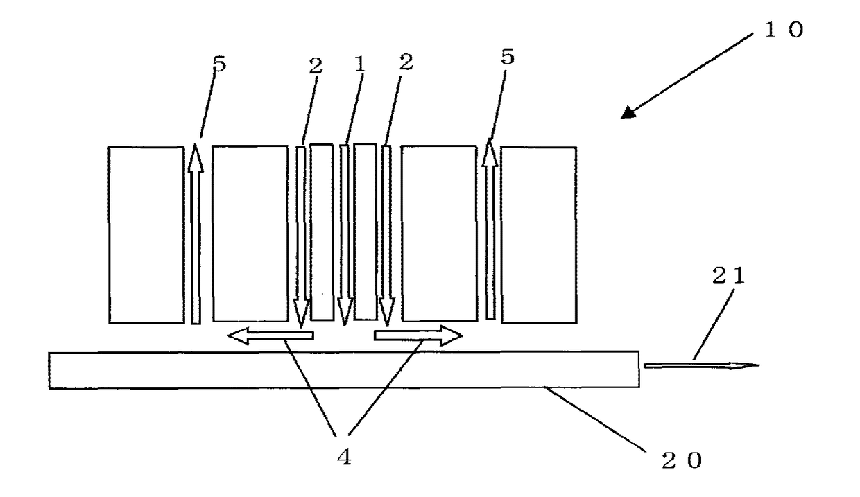
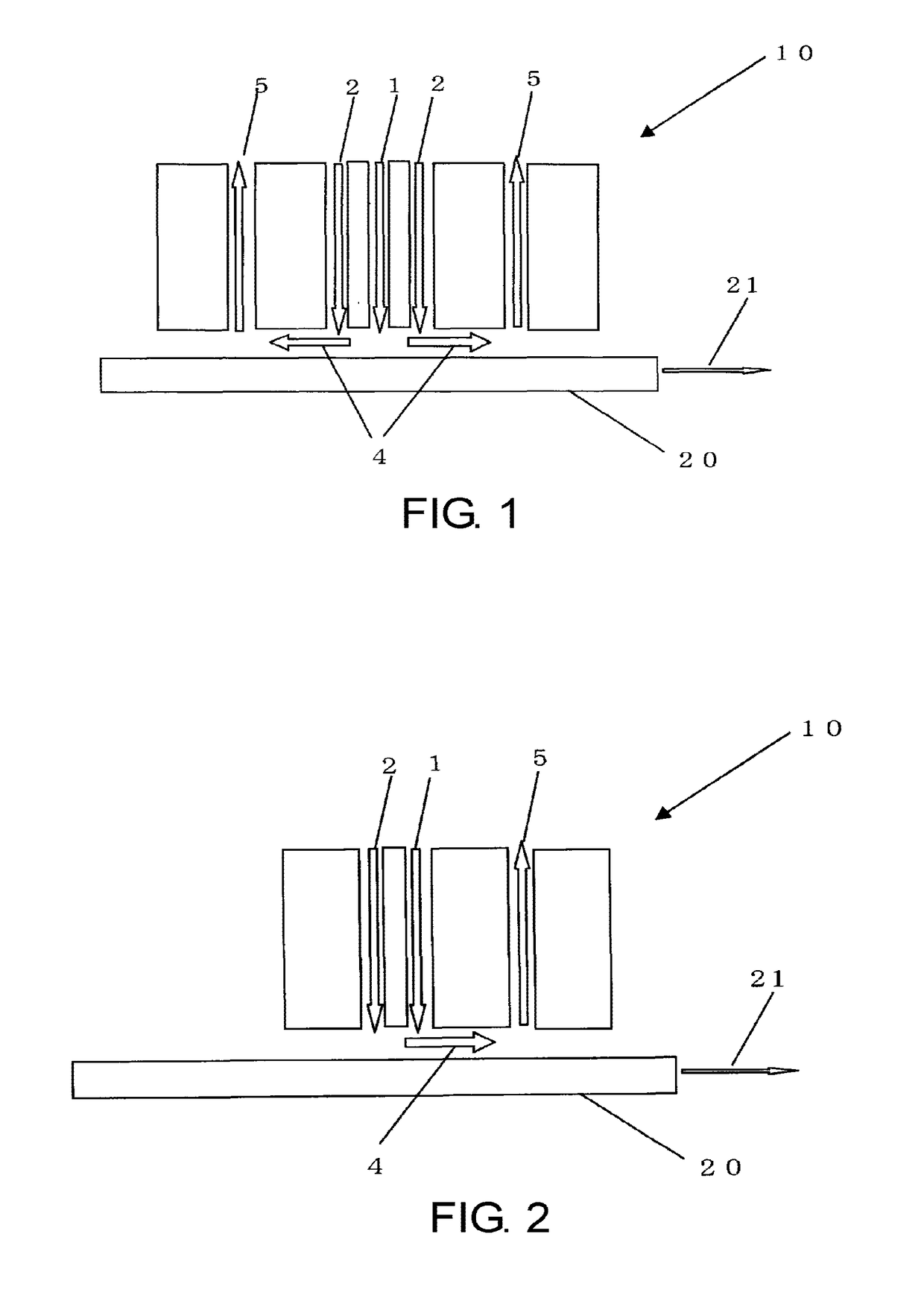
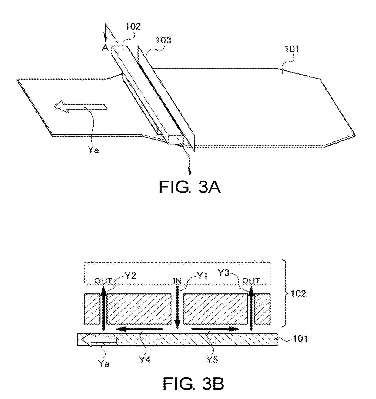
[0199]In a float bath where a glass ribbon of the glass material A was flowing, a fluorine treatment of the top surface was conducted under the conditions shown below with an HF gas.
[0200]Example 1: HF gas 6 (vol %), treatment time 3.5 seconds, treatment temperature 830° C.
[0201]Example 2: HF gas 5 (vol %), treatment time 3.5 seconds, treatment temperature 830° C.
[0202]Example 3: HF gas 4 (vol %), treatment time 3.5 seconds, treatment temperature 830° C.
[0203]Example 4: HF gas 2 (vol %), treatment time 3.5 seconds, treatment temperature 830° C.
examples 5 to 8
[0204]In a float bath where a glass ribbon of the glass material A was flowing, a fluorine treatment of the top surface was conducted under the conditions shown below by using an HF gas and thereafter, a dealkalization treatment of the top surface was conducted under the conditions shown below by using SO3 in a lehr.
[0205]Example 5: HF gas 6 (vol %), treatment time 3.5 seconds, treatment temperature 830° C.→in the lehr, SO3 about 5 (vol %), spraying treatment in zone at a temperature of 500 to 550° C.
[0206]Example 6: HF gas 5 (vol %), treatment time 3.5 seconds, treatment temperature 830° C.→in the lehr, SO3 about 5 (vol %), spraying treatment in zone at a temperature of 500 to 550° C.
[0207]Example 7: HF gas 4 (vol %), treatment time 3.5 seconds, treatment temperature 830° C.→in the lehr, SO3 about 9 (vol %), spraying treatment in zone at a temperature of 500 to 550° C.
[0208]Example 8: HF gas 2 (vol %), treatment time 3.5 seconds, treatment temperature 830° C.→in the lehr, SO3 about...
PUM
| Property | Measurement | Unit |
|---|---|---|
| Length | aaaaa | aaaaa |
| Length | aaaaa | aaaaa |
| Length | aaaaa | aaaaa |
Abstract
Description
Claims
Application Information
 - R&D
- Intellectual Property
- Life Sciences
- Materials
- Tech Scout
- Unparalleled Data Quality
- Higher Quality Content
- 60% Fewer Hallucinations
Browse by: Latest US Patents, China's latest patents, Technical Efficacy Thesaurus, Application Domain, Technology Topic, Popular Technical Reports.
© 2025 PatSnap. All rights reserved.Legal|Privacy policy|Modern Slavery Act Transparency Statement|Sitemap|About US| Contact US: help@patsnap.com


