Knee joint for orthosis

Inactive Publication Date: 2006-09-21
HATTON DALE L +2
View PDF13 Cites 63 Cited by
  • Summary
  • Abstract
  • Description
  • Claims
  • Application Information

AI Technical Summary

Benefits of technology

[0016] It is also an object of the present invention to provide for a knee joint orthosis that is mechanically simple to construct and durable.
[0017] It is also an objec

Problems solved by technology

Such designs do not allow for a natural movement of the leg, however, since the knee cannot bend during walking.
Due to the manner in which the teeth are cut, the joint allows movement in the extension direction but does not allow movement in the flexion direc

Method used


Image

  • Knee joint for orthosis
  • Knee joint for orthosis
  • Knee joint for orthosis

Examples


Embodiment Construction

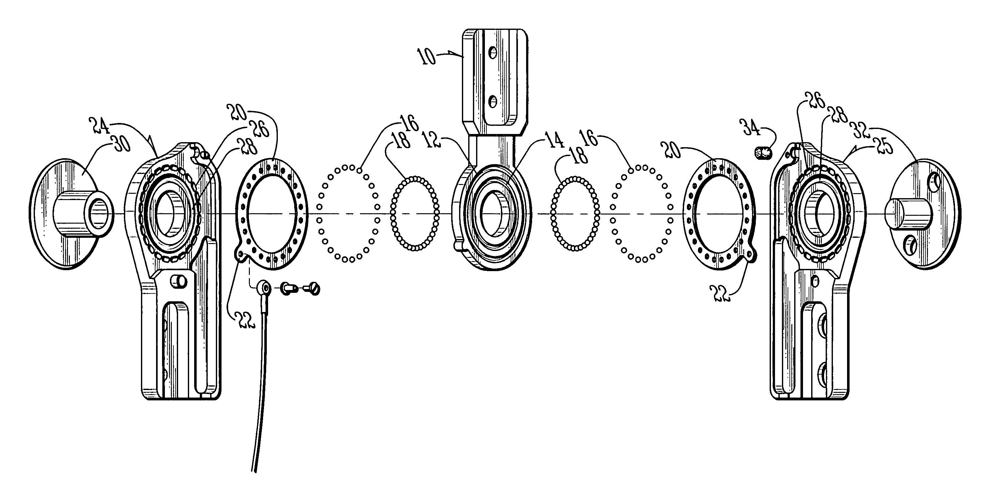
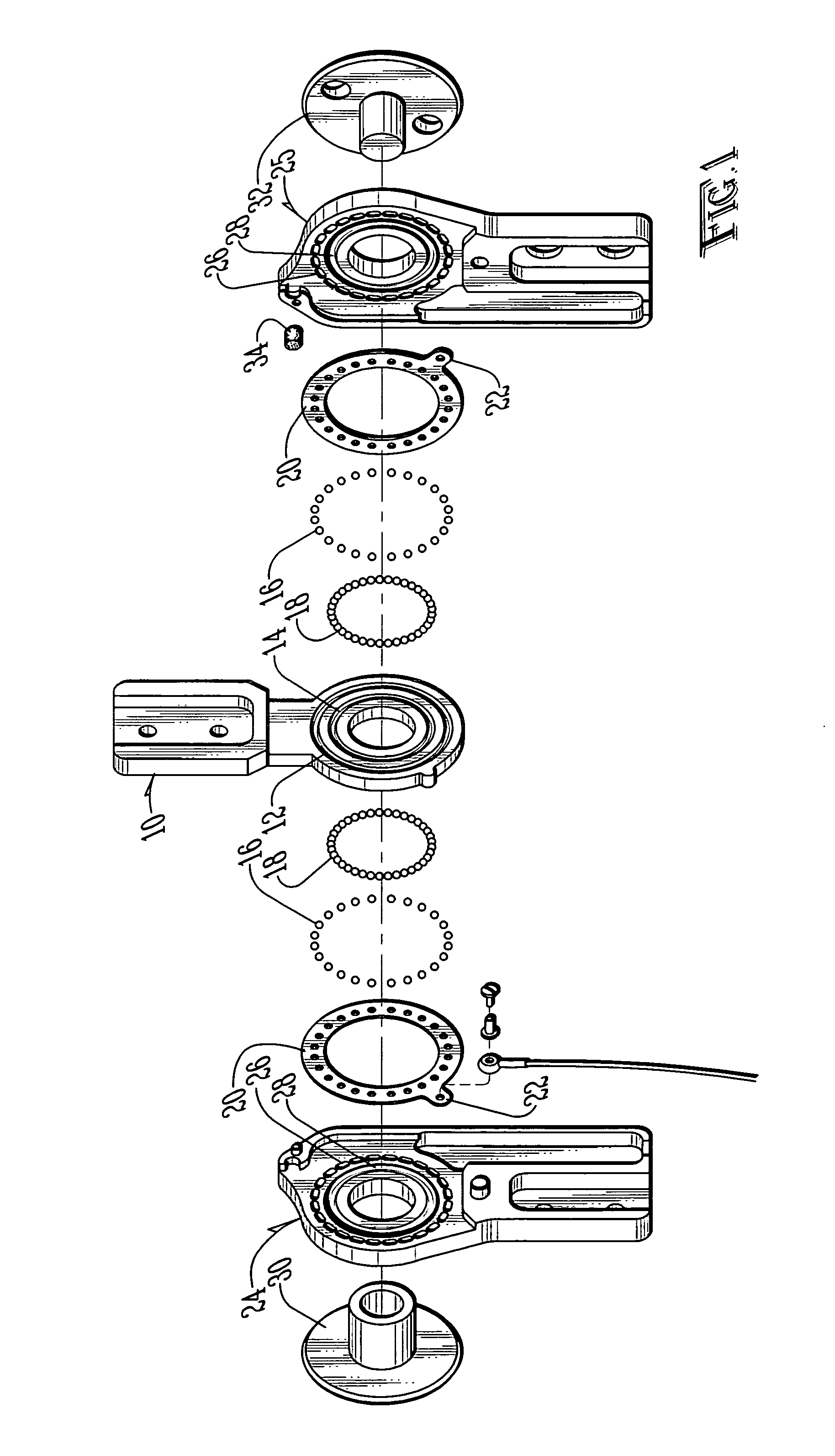
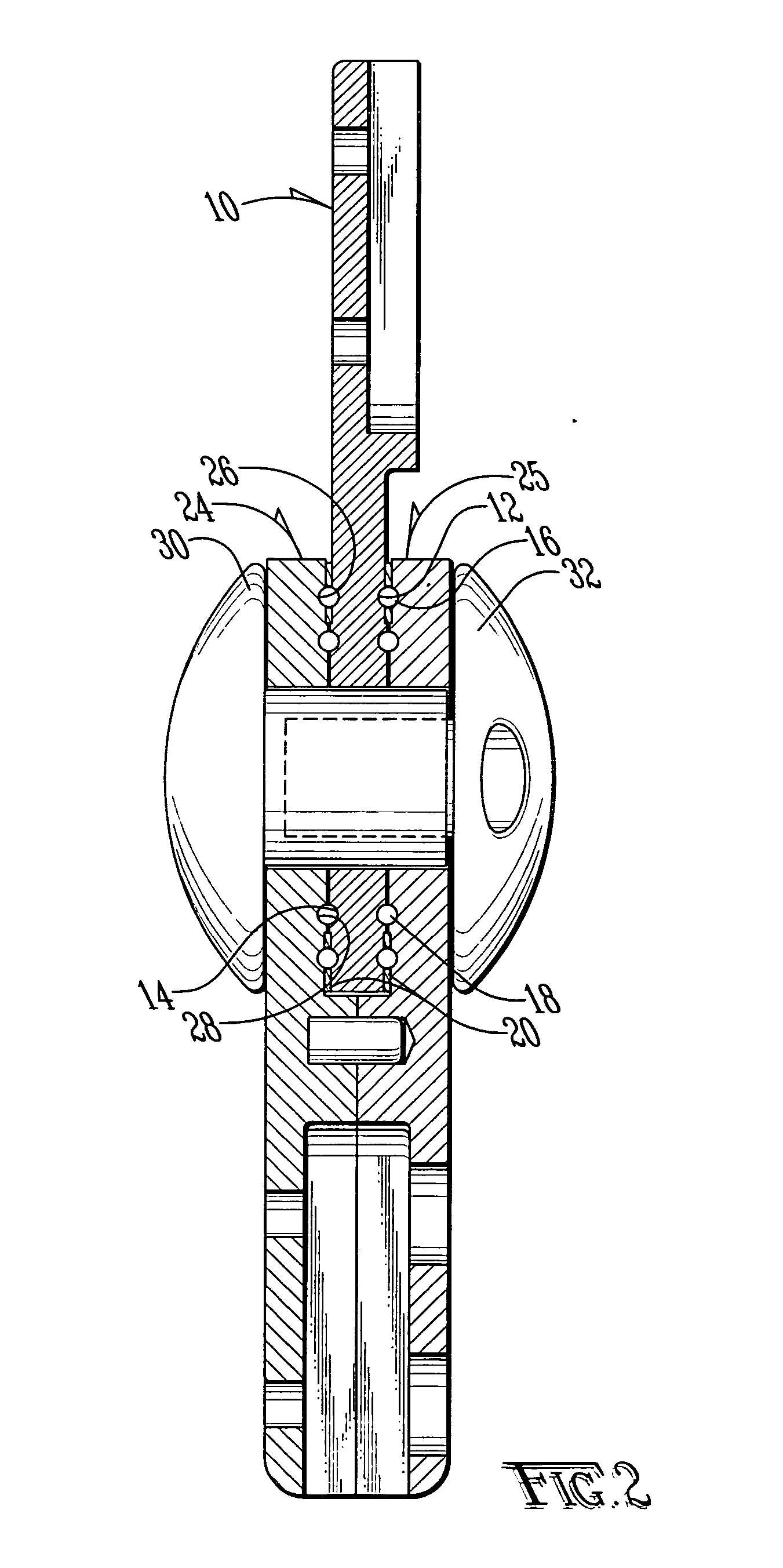
[0025] With reference to FIGS. 1 and 2, the principal components of a preferred embodiment of the present invention may now be described. Upper arm 10 is configured to be attached to the upper rigid portion of an orthosis (not shown) that is fitted to a patient's upper leg. On the face of each side of upper arm 10 is an upper thrust bearing race 14. Circumscribing upper thrust bearing race 14 is upper lock bearing race 12. Both upper thrust bearing races 14 and upper lock bearing races 12 are annular depressions in the face of upper arm 10. Preferably, upper arm 10 is formed of steel or a similarly strong material, and upper thrust bearing races 14 and upper lock bearing races 12 are machined into the faces of upper arm 10.

[0026] Resting in upper thrust bearing races 14 and upper lock bearing races 12 are thrust bearings 18 and lock bearings 16, respectively. Thrust bearings 18 provide for smooth rotation of upper arm 10 with respect to lower arms 24 and 25. Lock bearings 16 provid...


PUM


Abstract

An orthosis knee joint using a lock bearing arrangement is disclosed. The joint uses lock bearings that move in individual, arcuate races. The lock bearings are manipulated by means of a bearing cage from a locked position to an unlocked position. The locking mechanism is provided by the ramped shape of the bottom of the individual bearing races; movement of the bearing cage pinches the bearings at the shallower end of the ramp when the lock is activated and rotational force is exerted in the flexion direction. Movement in the extension direction, however, is still allowed in the locked position.

Description

BACKGROUND OF THE INVENTION [0001] This application claims benefit of U.S. provisional patent application Ser. No. 60 / 661,995, entitled “Knee Joint for Orthosis” and filed on Mar. 14, 2005. The entire disclosure of such provisional patent application is incorporated herein by reference. [0002] The present invention relates to knee joints for orthoses, and in particular to knee joints that are capable of selectively locking and unlocking in response to user motion. [0003] For many years, orthopedic appliances have been used to provide support and control for a patient who has temporarily or permanently lost muscular or neurological control of a limb. Leg orthoses (or braces) designed for this purpose must have some means to allow the leg to bend at the knee. Leg braces thus typically consist of three. principal components: a structure rigidly attached to the upper leg, a structure rigidly attached to the lower leg, and a joint or joints at the knee connecting the upper and lower leg ...

Claims


Application Information

Patent Timeline
IPC IPC(8): A61F5/00
CPCA61F5/0125A61F2005/0158
Inventor HATTON, DALE L.WALLACE, ZANE G.HORTON, GARY W.
Owner HATTON DALE L
Why Eureka
Try Eureka