Oscillating scanning probe with constant contact force

a scanning probe and constant contact technology, applied in the direction of mechanical measuring arrangements, instruments, mechanical means, etc., can solve the problems of affecting the scanning accuracy of the surface of the workpiece, affecting the accuracy of the scanning process, so as to prevent the bending of the stylus and the scanning flexibility and accuracy. , the effect of improving the scanning flexibility

Active Publication Date: 2010-08-24
HEXAGON METROLOGY A B (SE)
View PDF16 Cites 70 Cited by
  • Summary
  • Abstract
  • Description
  • Claims
  • Application Information

AI Technical Summary

Benefits of technology

[0014]According to this method, the scanning can be performed in with a greater scanning flexibility and accuracy when the surfaces' forms are unusual or complex in three dimensions. Indeed, the adjustment of the contact force according to the surface profile prevents the bending of the stylus. In a preferred embodiment of the invention, when the adjustment cannot constrain the contact force within a predefined boundary value, further corrections can be made. The cinematic effects due to inertia forces can be also be considered for the adjustment of the contact force.

Problems solved by technology

One major drawback of such methods known from the art is that they are relatively slow since the whole machine needs to be moved backwards and forwards while covering the whole scanning area of the surface.
Furthermore, the accelerations and decelerations of the machine can introduce inaccuracies in the measurement process because of the strong inertia forces due to the heavy weight of the pieces in charge of positioning the surface detecting device.
As a result, some pieces can be bent when the deflection forces applied are too high, and the measurement results are flawed.
Nevertheless, there is no method disclosed in the prior art that would allow to scan efficiently a complex surface whose form spans in the three dimensions of space, whereby the scanning would be done with non rectilinear movements and the force applied to the surface would yet still be kept constant or within a predefined range.

Method used


Image

  • Oscillating scanning probe with constant contact force
  • Oscillating scanning probe with constant contact force
  • Oscillating scanning probe with constant contact force

Examples


Embodiment Construction

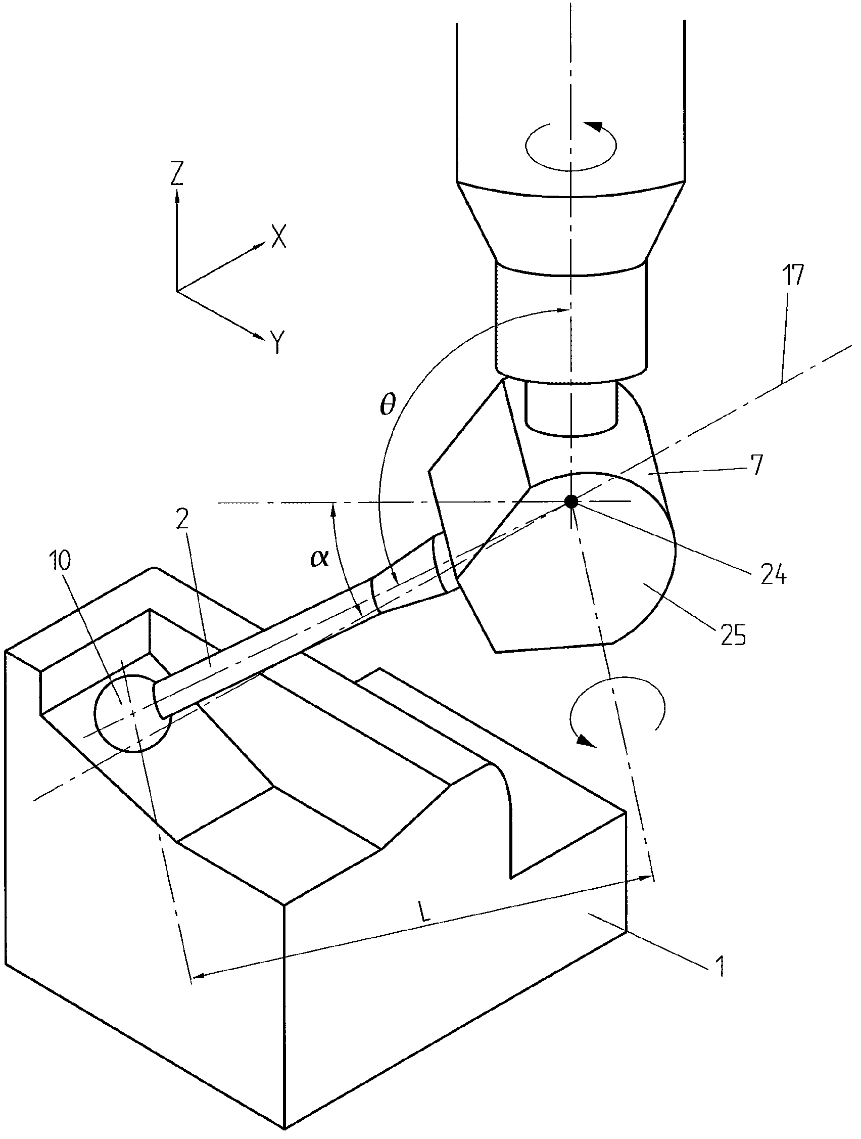
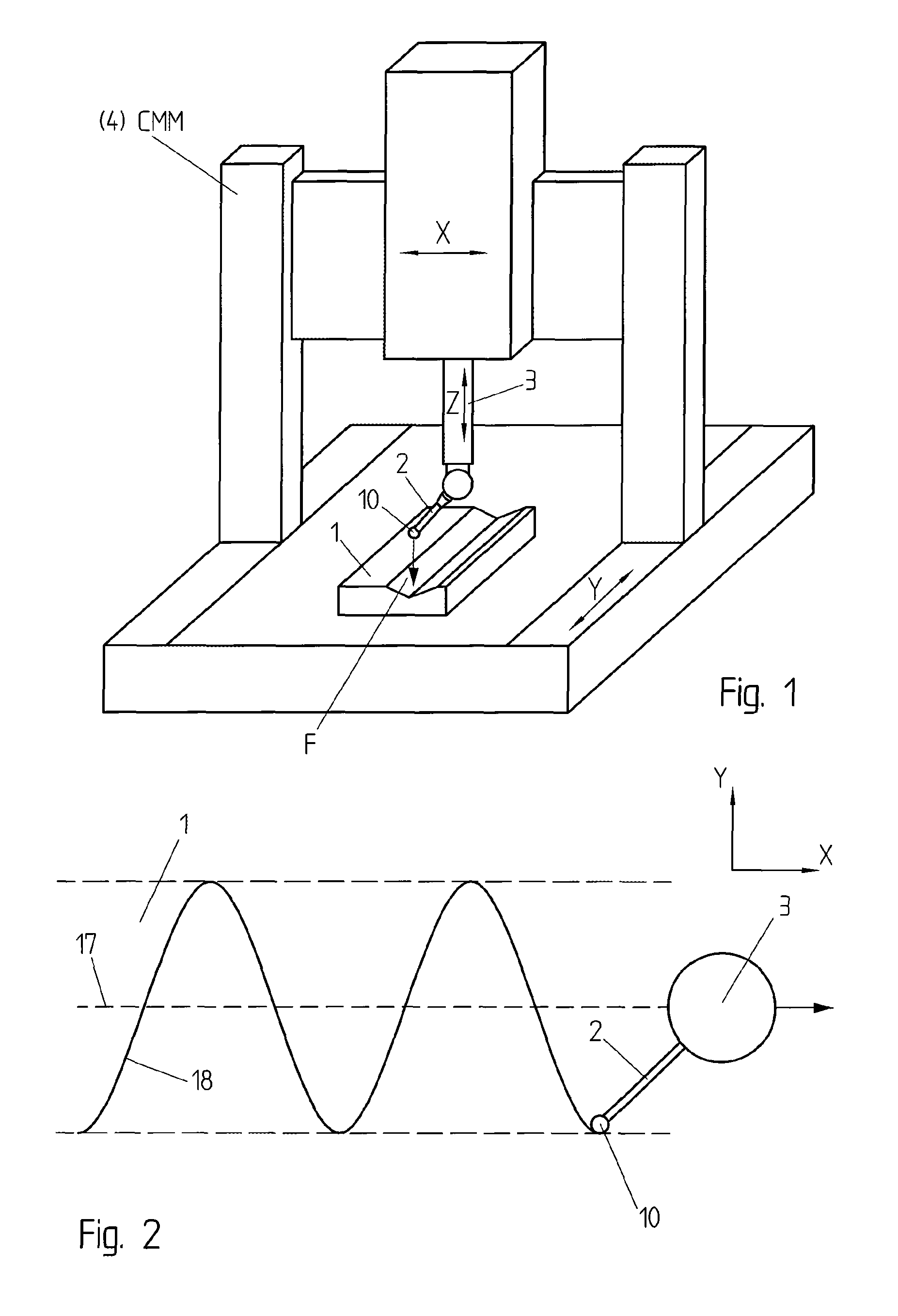
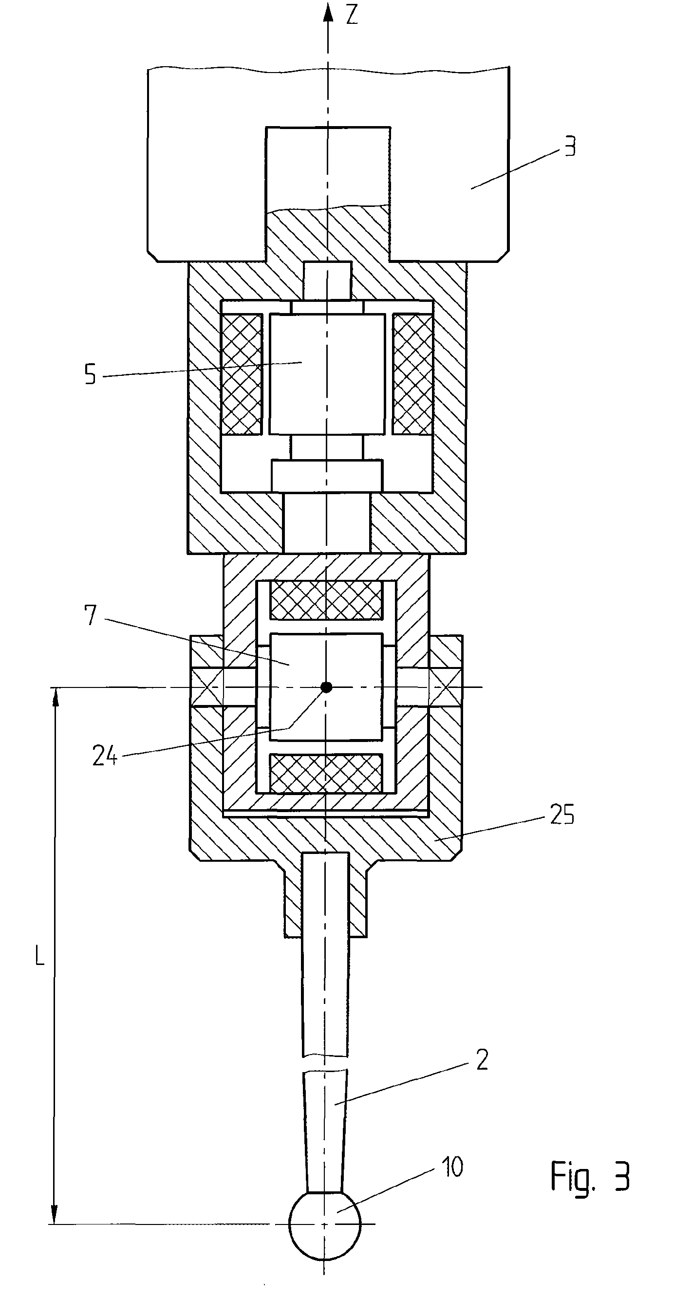
[0023]A coordinate measuring machine, also known as CMM 4, is disclosed in FIG. 1 according to a preferred embodiment of the invention, where the support 3 can be moved in any linear direction (X, Y, Z), and the scanning probe 2 is attached to the support 3 while having two degrees of freedom in rotation with respect to the support 3. In this example, the axes for the rotation are the axis Z and Y, but other combinations of axes could be considered (e.g. X and Y). The tip of the probe 10, preferably spherical, is in contact with the surface 1 that is supposed to be scanned. The contact force F between the tip of the probe 10 and the surface to scan 1 is defined as the opposite of the reaction applied by the surface on the probe tip 10. This contact force F is hence normal to the plane tangent to the point of contact with the surface 1; in other words, the contact force always acts normally on the surface 1.

[0024]FIG. 2 shows a potential scanning path projected on the plane (x,y). Th...


PUM


Abstract

A method for scanning a surface of a workpiece using a scanning probe 2 mounted on a support 3 on a coordinate measuring machine 4. The support contains drive means 5, 7 for actuating the movement of the scanning probe 2 relatively to the support 3. The method further involves detecting means 9 to measure a contact force F applied between the tip 10 of the probe and the surface 1, control means 13 coupled to the drive means, and memory means 14 for storing theoretical profiles 19 and coordinates 20 of the surface. This method is characterized by the fact that the control means 13 adjust the actuation of the drive means 5, 7 along a scanning path 18 in order to maintain the contact force 11 within the defined range of values 15 during the whole scanning operation along the scanning path 18.

Description

REFERENCE DATA[0001]The present invention claims priority from European Patent Application N. 2007EP-105559, filed on Apr. 3, 2007.FIELD OF THE INVENTION[0002]The present invention concerns a method for scanning the surface of a workpiece and a related apparatus.DESCRIPTION OF RELATED ART[0003]Numerous methods for scanning are known, in which a mechanical probe is fixed on a machine spindle which traverses the surface of a workpiece in straight lines over each possible direction (X, Y, Z). After each line is completed the machine spindle moves the probe to a new position displaced from the completed line and repeats the movement along a parallel line.[0004]One major drawback of such methods known from the art is that they are relatively slow since the whole machine needs to be moved backwards and forwards while covering the whole scanning area of the surface. Furthermore, the accelerations and decelerations of the machine can introduce inaccuracies in the measurement process because...

Claims


Application Information

Patent Timeline
Patent Type & Authority Patents(United States)
IPC IPC(8): G01B5/012G01B7/012
CPCG01B21/04G01B3/008
Inventor JORDIL, PASCALPETTERSSON, BOKNUT, SIERCKS
Owner HEXAGON METROLOGY A B (SE)
Why Eureka
Try Eureka