Bone screw holding device

a technology for bone screws and holding devices, which is applied in the field of devices and methods for inserting bone screws, can solve the problems of bone screws that are not secured to the driver, can slip, become lost in the tissue, and increase the operating time without unnecessary and undesirable effects, and achieve the effect of smooth sliding

Inactive Publication Date: 2008-10-30
STRYKER CORP
View PDF41 Cites 70 Cited by
  • Summary
  • Abstract
  • Description
  • Claims
  • Application Information

AI Technical Summary

Benefits of technology

[0009]The fixation sleeve has a distal end, a proximal end and a tubular body connecting the distal end and the proximal end. The fixation sleeve is hollow, the hollow portion having a diameter sufficiently large to allow the screw engaging part to smoothly slide in the fixation sleeve. A disk may be formed at the proximal end of the fixation sleeve which may be used to assist in pushing or pulling the fixation sleeve with respect to the screw engaging part.
[0010]The screw engaging part and the fixation sleeve are assembled together to form the screw holding device. In the assembled state, the screw engaging part and the fixation sleeve slide relative to each other. When the fixation sleeve is moved towards the proximal direction, the two halves of the screw engaging part are able to flex easily towards each other. When the fixation sleeve is moved towards the distal end of the screw engaging part, the two halves of the screw engaging part are prevented from flexing towards each other.
[0011]In use, the fixation sleeve may slide in the proximal direction and the distal tip of the screw engaging part may be pressed against the edges of the recess, thereby inserting the distal tip of the screw engaging part into the recess. When the distal tip of the screw engaging part is pressed against the edges of the recess, the two halves of the screw engaging part are pushed towards each other allowing the distal tip of the screw engaging part the ability to enter the recess. As the tip of the distal part of the screw engaging part travels further in the distal direction into the recess, it reaches the notch and the hooks engage in the notch allowing the two halves of the screw engaging part to flex away from each other. The seating of the hooks in the notch prevents the screw holding device from disengaging from the screw accidentally. At this point, the fixation sleeve positioned distally as far as possible to prevent the two halves of the screw engaging part from flexing towards each other and thereby ensuring that the screw is securely attached to the screw holding device.

Problems solved by technology

Often, a surgeon needs to install a large number of bone screws.
Bone screws that are not secured to the driver can slip and become lost in the tissue.
This results in unnecessary and undesirable increase in operating time.
Prior art screw and driver system that capture the screw prior to insertion do not provide rigid attachment of the screw to the driver and therefore, have the same shortcoming as the traditional screw and screw driver.

Method used


Image

  • Bone screw holding device
  • Bone screw holding device
  • Bone screw holding device

Examples


Embodiment Construction

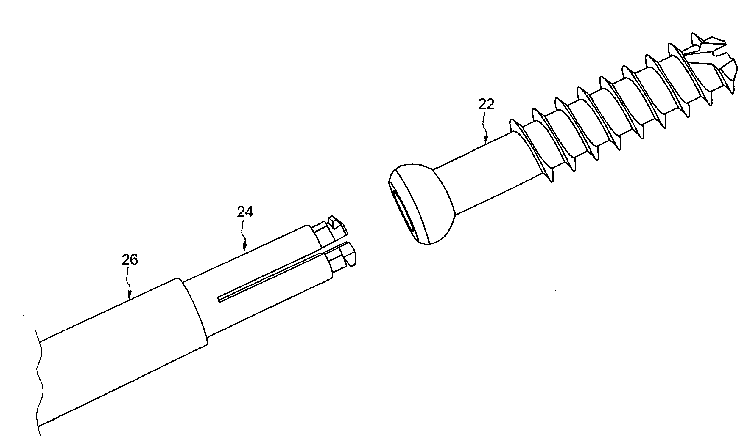
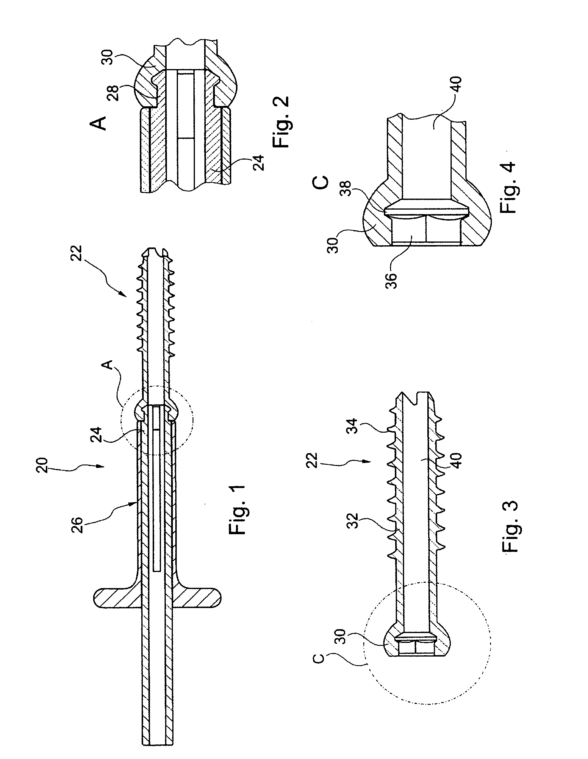
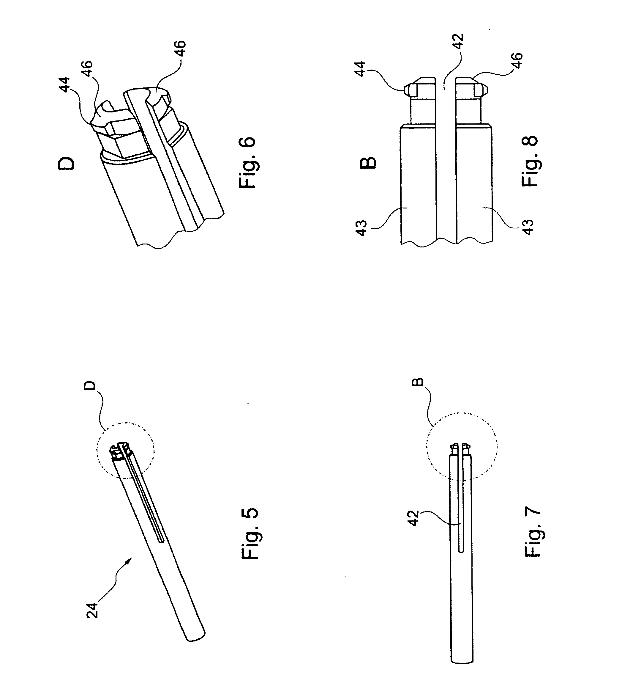
[0037]FIGS. 1 and 11 show a screw holding device 20 engaged with a screw 22. FIGS. 18-25 depict various components of screw holding device 20 in various state of assembly and in engagement with screw 22. Screw holding device 20 has a screw engaging part 24 and a fixation sleeve 26. FIG. 2 is an enlarged view of the distal portion of screw engaging part 24 and screw 22. FIG. 2 shows a tip 28 of screw engaging part 24 inserted into a head 30 of screw 22.

[0038]Screw 22 is depicted in a side view in FIG. 12, an isometric view in FIG. 13, and cross-sectional views in FIGS. 3 and 4. Screw 22 includes head 30 and a shaft 32 having threads 34. Threads 34 may be selected from the various types of threads known to one skilled in the art. Screw 22 may be used as a bone screw. Head 30 has a recess 36 having six facets. However, recess 36 may be of any suitable shape known to one skilled in the art, non-limiting examples of which include any type of polygon, oval, oblong or star shape. There may...


PUM


Abstract

A screw holding device has a screw engaging part and a fixation sleeve. The screw for use with the screw holding device has a head and a shaft. The head of the bone screw has a recess and a notch. The screw engaging part has two halves with a hook formed on each half. The hook is shaped to fit in the notch. A fixation sleeve slides over the screw engaging part. When the fixation sleeve is pulled in proximal direction, the two halves of the screw engaging part are able to flex easily towards each other and thereby are insertable in the recess. When the fixation sleeve is moved towards the distal end of the screw engaging part, the two halves of the screw engaging part are prevented from flexing towards each other and thereby rigidly lock the screw and the screw engaging part together.

Description

CROSS-REFERENCE TO RELATED APPLICATIONS[0001]This application claims the benefit of the filing date of U.S. Provisional Patent Application No. 60 / 922,599 filed Apr. 10, 2007, the disclosure of which is hereby incorporated herein by reference.BACKGROUND OF THE INVENTION[0002]1. Field of Invention[0003]The present invention relates to a device and method for inserting bone screws during a surgical procedure. More particularly, the present invention relates to an improved system of a bone screw holding device and a bone screw wherein the bone screw is held rigidly prior to and during insertion.[0004]2. Description of the Related Art[0005]Many types of bone screws are available for use with specific type of bone tissue or orthopedic implants. Often, a surgeon needs to install a large number of bone screws. Bone screws that are not secured to the driver can slip and become lost in the tissue. This results in unnecessary and undesirable increase in operating time. Therefore, it is desirab...

Claims


Application Information

Patent Timeline
Patent Type & Authority Applications(United States)
IPC IPC(8): A61B17/58B25B13/00B25B13/48
CPCA61B17/861A61B17/8888B25B23/108
Inventor SCHWAGER, MANUELDORAWA, KLAUS
Owner STRYKER CORP
Why Eureka
Try Eureka