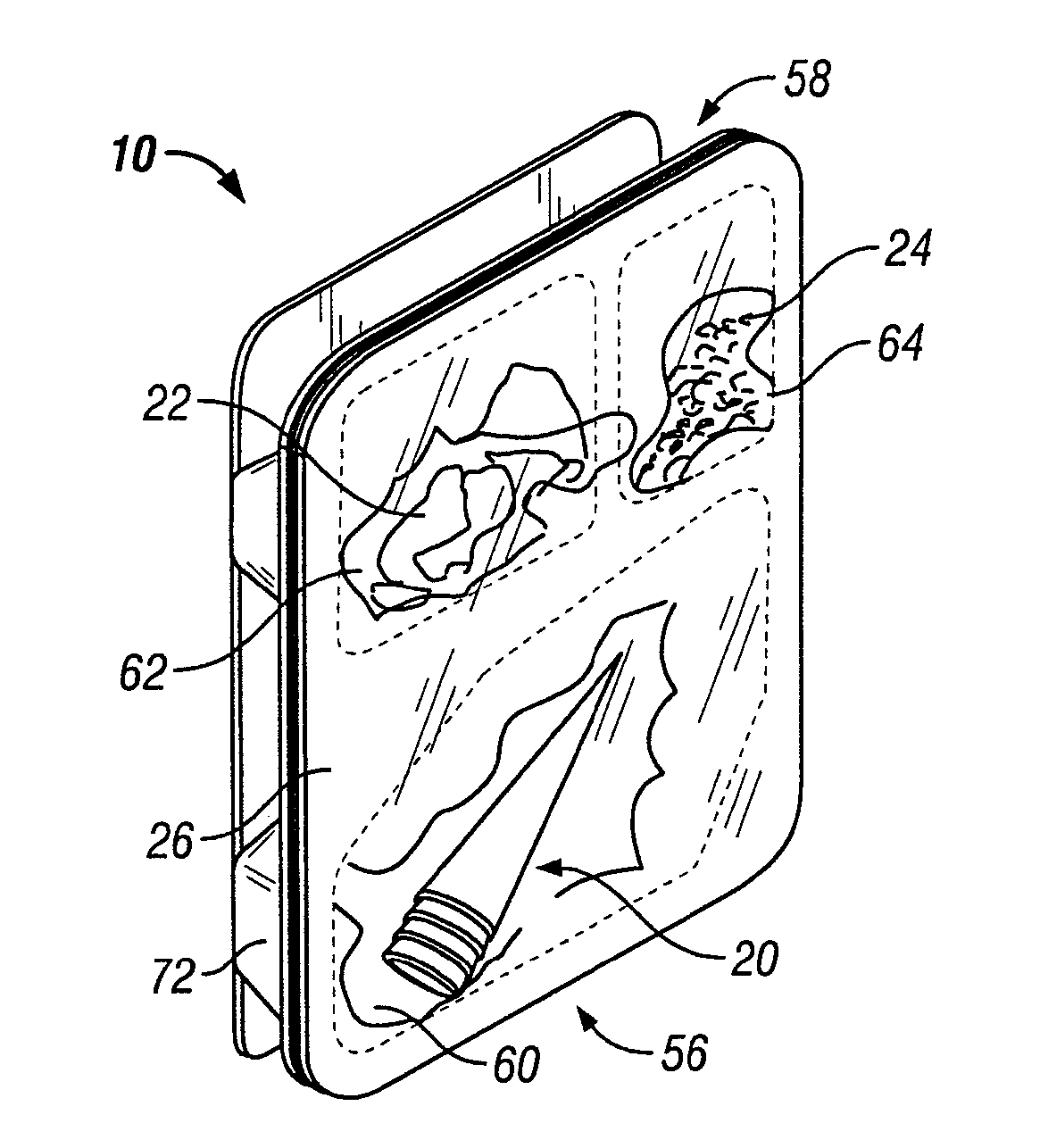
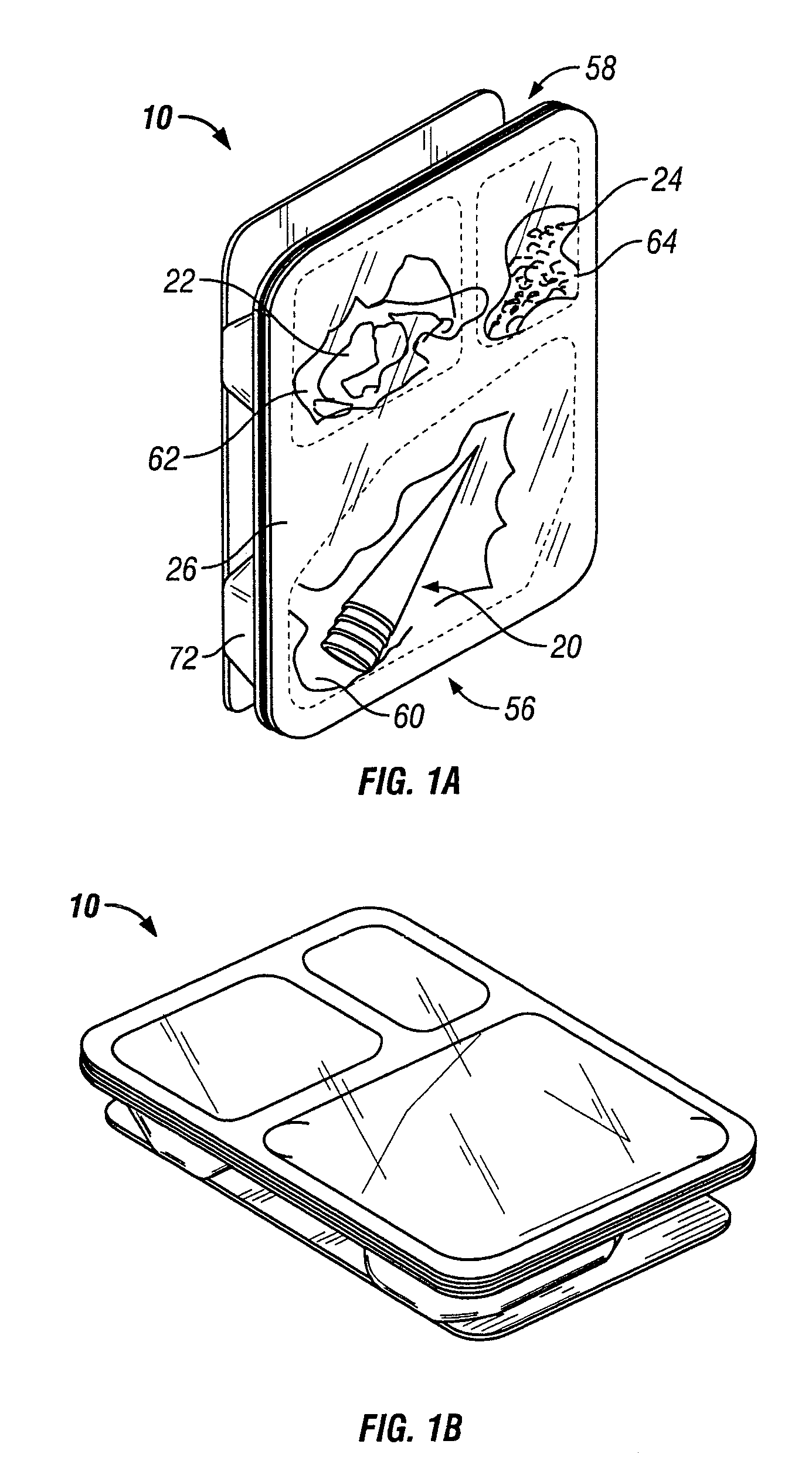
[0009] In accordance with the present invention, a food package is provided that includes a holding portion which allows a user such as children to place a food item carried by the package in a stationary position therein so that other filling and / or topping food-type items can be applied thereto. In this manner, the present food package provides a staging area that a child can use instead of placing the filling / topping receiver food item on a support surface for this purpose. In the preferred form, the holding portion has a conical configuration to act as a cone holder for cones carried in the package. This allows a user to remove one of the cones from a compartment and place it in a stationary vertical orientation in the cone holder for filling it with food products, viz. cream filling and sprinkles or M&Ms, carried in other compartments of the package base member. Alternatively, food items not carried by the package can also be combined with the held food item. Further, when the filled cone is not being eaten such as after several bites have been taken therefrom, the child can place the partially eaten cone into the cone holder as a convenient resting location so that any product filling and toppings thereon protruding from the cone are kept off of any support surface onto which the cone might otherwise be placed. Generally, the holding portion will have a matching configuration to that of the portion of the food item to be placed therein so that it is stable when held thereby.
[0010] In adding the holding portion and in particular the cone holder to the base portion, one consideration is that the material of the base member not be thinned to the point where its ability to act as a moisture barrier becomes compromised. In other words, the plastic material of the base member needs to be of sufficient thickness to provide a good moisture barrier for the food products retained in the compartments of the package, particularly where such products include sugar or wafer cones that are highly susceptible to damage via access of moisture thereto. Accordingly, in one form, the generally conical configuration of the holding portion has a tripod configuration which includes three projecting legs that can engage against the tip end of the cone when placed therein. By having a tripod configuration, a greater amount of plastic material can be employed in the cone holder area thus minimizing any thinning of a plastic material therein and keeping moisture from permeating into the cone compartment.
[0011] As mentioned, the base members are typically stacked during production thereof. Accordingly, the base members are provided with stacking lugs so as to keep adjacent bottom walls of respective stacked base members spaced from each other for ease in denesting the stacked base members from one another. Given the normal space constraints in the base members in these types of compact food packages generally, one form of the invention provides the cone holders in the stacking lug areas. As the stacking lugs include a flat, horizontal platform surface that can create hangup points for of the food products as they are inserted into the compartments during production, the combination of the holding portion drawn down from the horizontal platform surfaces keeps these hangup locations to a minimum. In other words, the holding portion need not be drawn down from a platform surface distinct from that of a lug so as to keep these horizontal surface hang-up locations to a minimum.
[0014] More specifically, the spacer wall extends obliquely between the upper seal surface and the main compartment side wall adjacent the bottom end of the base member so that this side wall does not depend directly from the seal surface. In this manner, the oblique spacer wall lifts the food items or cones in the main compartment into alignment for proper viewing through the main compartment window of the seal member. The spacer wall thus maximizes the surface area on the seal member for receiving printed matter between the main compartment view window and the end of the base. An additional advantage as previously discussed is that the obliquely oriented spacer wall serves as a lead-in or ramp surface for cones that are being placed into the main compartment, albeit slightly out of alignment therewith. Rather than getting hung up on the seal surface that would otherwise be in this position immediately about the perimeter of the compartment, the cone will engage on the obliquely inclined ramp surface leading the cone into the main compartment.
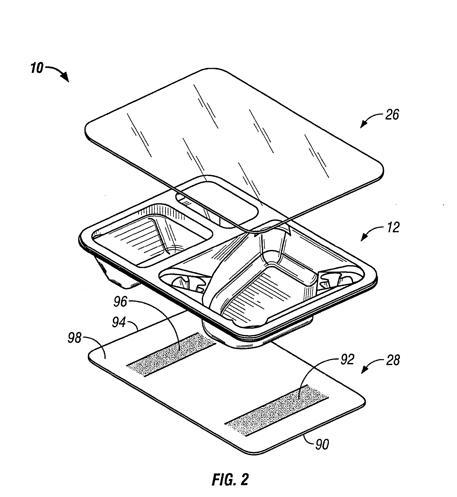
[0016] Preferably, the bottom walls of the compartments are flat and coplanar so as to allow the back card to be adhered to both the main compartment as well as the smaller compartments. So adhered, the card member acts as a stiffener for the base member to resist flexing thereof as can be caused by peeling of the seal film therefrom. Accordingly, the present package assembly is better able to avoid having its contents be ejected therefrom when the pull force on the seal member is released and the flexed base member rebounds back to its original undeformed configuration. In prior packages of this type, the back card member did not extend for the full length of the upper compartments and was not adhered thereto thus not providing the stiffening effect of the present elongate card member adhered to both the upper and lower compartments along the length of the base member.
[0017] Additionally, since the card member extends further up along the base member, and preferably past the bottom walls of the upper compartments, the card also allows the packages to be stacked more readily one on top of the other in proper alignment for being shrink-wrapped together. Normally, the stacking machine will advance one package over another for sliding over the top of the lower package. With the extra length of the back card member, it acts as a slide or sled for the upper package as it engages the seal member of the lower package to allow it to slide smoothly thereon into proper aligned position for being shrink-wrapped thereto.

