Dynamic, hierarchical data exchange system

a data exchange and hierarchical technology, applied in the field of networked computer systems, can solve the problems of large size, large development and modification cost, complex programming to write and maintain,

Inactive Publication Date: 2007-01-16
X AWARE
View PDF1 Cites 177 Cited by
  • Summary
  • Abstract
  • Description
  • Claims
  • Application Information

AI Technical Summary

Benefits of technology

[0025]5. A Join operation is provided, similar to the database Join operation, but with extension to work against hierarchical data, and data from any available source, not just database data.
[0026]Further objects and advantages of the present invention will become apparent from a consideration of the drawings and ensuing description.
[0027]The present invention overcomes the limitations of the prior art by providing a highly flexible Hierarchical Data Server (HDS) and accompanying Document Definition Authoring System. The Authoring System creates Document Definition Files (DDF), which specify hierarchically related elements, each of which is capable of generating dynamic data. A Client sends a request to the HDS, indicating which DDF is desired, and a list of parameter substitutions that the HDS is to apply to the DDF. The HDS processes all elements in the DDF, dynamically generating data, then outputs the data in a format requested by the Client.
[0028]FIG. 15 shows an overview of the HDS and Authoring System. A Client system 200 requiring data from various Enterprise System 202, including databases, hosts, and any other data source, will arrange for a new DDF 204 to be created using the Authoring System 203. The Authoring System 203 is used to define the structure and data sources for each element of data requested, and the parameters that can be used to customize the DDF 204 for any particular Client's purpose. The DDF 204 is stored in a location convenient for the HDS 201 to access it upon request.
[0029]When the Client 200 needs the data, it sends a request over the interface 205 to the HDS, specifying the DDF name and any needed parameters. The HDS 201 reads the DDF into memory, performs parameter substitution, and executes each element. The execution of elements is expected to cause a plurality of data requests to be processed over the Data Transactions Interface 206, retrieving data from the various Enterprise Systems 202, and returning the data over the interface to be placed in a DDF element on the HDS 201. After all elements are fully executed, the HDS 201 formats the resulting data into a Data File, and transmits the Data back to the Client 200 over the interface 205.

Problems solved by technology

Such programs are complex to write and maintain, require great expense to development and modify, and are large in size due to the amount of code required for the large number of interfaces.
More advanced systems perform some data retrievals in parallel, but the complexity of this type of system requires greatly more experienced programmers and testers, thus significantly increasing the cost of system development.
Finally, the code developed to interface to each system and each data source is not easily reused in other systems in the enterprise for a variety of reasons.
Some reasons for low success rate of reuse are the fact that programs perform vastly different functions (service vs. billing), so developers often do not recognize the possibilities of reusing code.
Tools to assist in reuse are not widely used, developers are generally slow to be convinced that existing components will precisely fit their needs, and current engineering practices that emphasize reuse have not been widely adopted in many corporations.
Unfortunately, many computer systems in large enterprise environments require interfaces customized for the particular Client and Server pair.
However, it is more often the case in large enterprise environments for Client 1 and Client 2 to be developed by separate groups, and the opportunity to reuse the code is not exploited.
A DBMS cannot process a request for an arbitrarily complex hierarchy in a single request, because requests to a DBMS are row-based.
For clients requiring less than the entire set of information, this very inefficient, as unneeded data is generated, formatted, and transmitted to the client.
But the join is limited to row-based tables, with the result of the join being row data.
However, if some or all of the data file is dynamic, an intricate program must be developed to produce the dynamic portions and insert them appropriately into the Data File.
However, these systems do not provide the capability to generate arbitrary levels of hierarchical data, so are limited in the complex data structures they can generate.
Such a method is difficult to change when the needs of the client system changes.

Method used


Image

  • Dynamic, hierarchical data exchange system
  • Dynamic, hierarchical data exchange system
  • Dynamic, hierarchical data exchange system

Examples


Embodiment Construction

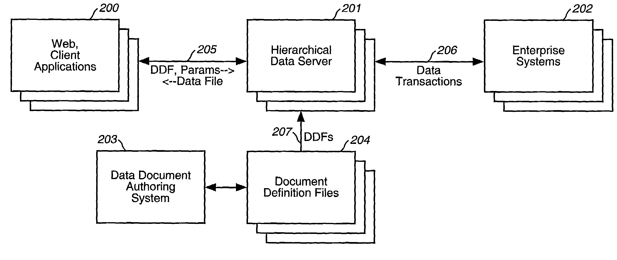
of Authoring System, presents the graphical computer program layout of an authoring system.

[0035]FIG. 5, System Parameter File, is an example parameter file used by a preferred embodiment of the invention to dictate processing by the Authoring System and the Hierarchical Data Server (HDS).

[0036]FIG. 6, Hierarchical Data Server Process, is a flowchart describing the processing steps of the preferred embodiment.

[0037]FIG. 7, Process Element, is a flowchart describing the processing steps taken by the HDS to process an element.

[0038]FIG. 8, Process Children, is a flowchart describing the processing steps taken by the HDS to process the children element of an element.

[0039]FIG. 9, Format Memory into Data File, is a flowchart describing the processing steps taken by the HDS to format DDF elements after they have been executed.

[0040]FIG. 10, Output Element, is a flowchart describing the processing steps taken by the HDS to format and output an element.

[0041]FIG. 11, SQL BuildSubtree, is a...


PUM


Abstract

A computer system provides the ability to construct and edit a Data Definition File (DDF) containing hierarchically related elements of data, some of which are dynamic in that they must execute in order to produce or retrieve data. A client computer system having knowledge of a DDF appropriate for its uses sends a request to a server, which contains or can retrieve the DDF requested by the client. The request contains parameters used by the server to customize the resulting keyed data file for the client's purposes. Upon receipt of the request, the server copies the DDF into a coupled memory, performs requested parameter substitutions, and executes dynamic elements to produce resulting data elements. The process is repeated recursively for all elements of the hierarchical structure, until no dynamic elements remain, then the resulting keyed data file is returned to the client for its uses. Data elements may be derived from a plurality of sources, and these sources may be combined and manipulated using a plurality of data operations, including relational algebra or structured query language, enabling joins and merges between multiple sources and formats. An Authoring System is provided which assists in the construction and validation of DDFs.

Description

CROSS REFERENCES TO RELATED APPLICATIONS[0001]This is a continuation of co-pending U.S. application Ser. No. 09 / 264,101, filed on Mar. 18, 1999, which application is hereby incorporated by reference herein.[0002]This application claims the benefit of Provisional Patent Application Ser. No. 60 / 077,259, Filed 1998, Mar. 9.FIELD OF THE INVENTION[0003]The present invention relates to networked computer systems in which a plurality of interconnected computer systems exchange data.BACKGROUND OF THE INVENTION[0004]The present invention relates to computer systems interconnected by a network, suitably configured to transfer data between one another. A computer system connected to the network processes data from a plurality of data sources. A data source can be an input device attached to the computer system, or can be a storage device, memory, database, or other computer system attached either locally or remotely to the computer system via a network. In the network of computers, at any give...

Claims


Application Information

Patent Timeline
Patent Type & Authority Patents(United States)
IPC IPC(8): G06F17/00G06F17/30
CPCG06F17/30389G06F17/30424G06F17/30917Y10S707/99942Y10S707/99943Y10S707/99933G06F16/245G06F16/86G06F16/242
Inventor VANDERSLUIS, KIRSTAN ANDERSON
Owner X AWARE
Why Eureka
Try Eureka