Clamping device

a technology of clamping device and shaft, which is applied in the direction of pliers, manufacturing tools, and spaces, can solve the problems of reducing the lifetime of the shaft, inconvenient operation for users, and easy wear of the shaft, so as to achieve the effect of reducing the disadvantage and/or obviating the disadvantag

Inactive Publication Date: 2006-09-21
WANG GUEI YING
View PDF3 Cites 34 Cited by
  • Summary
  • Abstract
  • Description
  • Claims
  • Application Information

AI Technical Summary

Benefits of technology

[0006] The present invention is to mitigate and/or obvia

Problems solved by technology

However, when the shaft is slidable relative to the socket, the shaft easily vibrates due to a gap between the shaft and the socket, thereby causing inconvenience to a user when operating the clampin

Method used


Image

  • Clamping device
  • Clamping device
  • Clamping device

Examples


Embodiment Construction

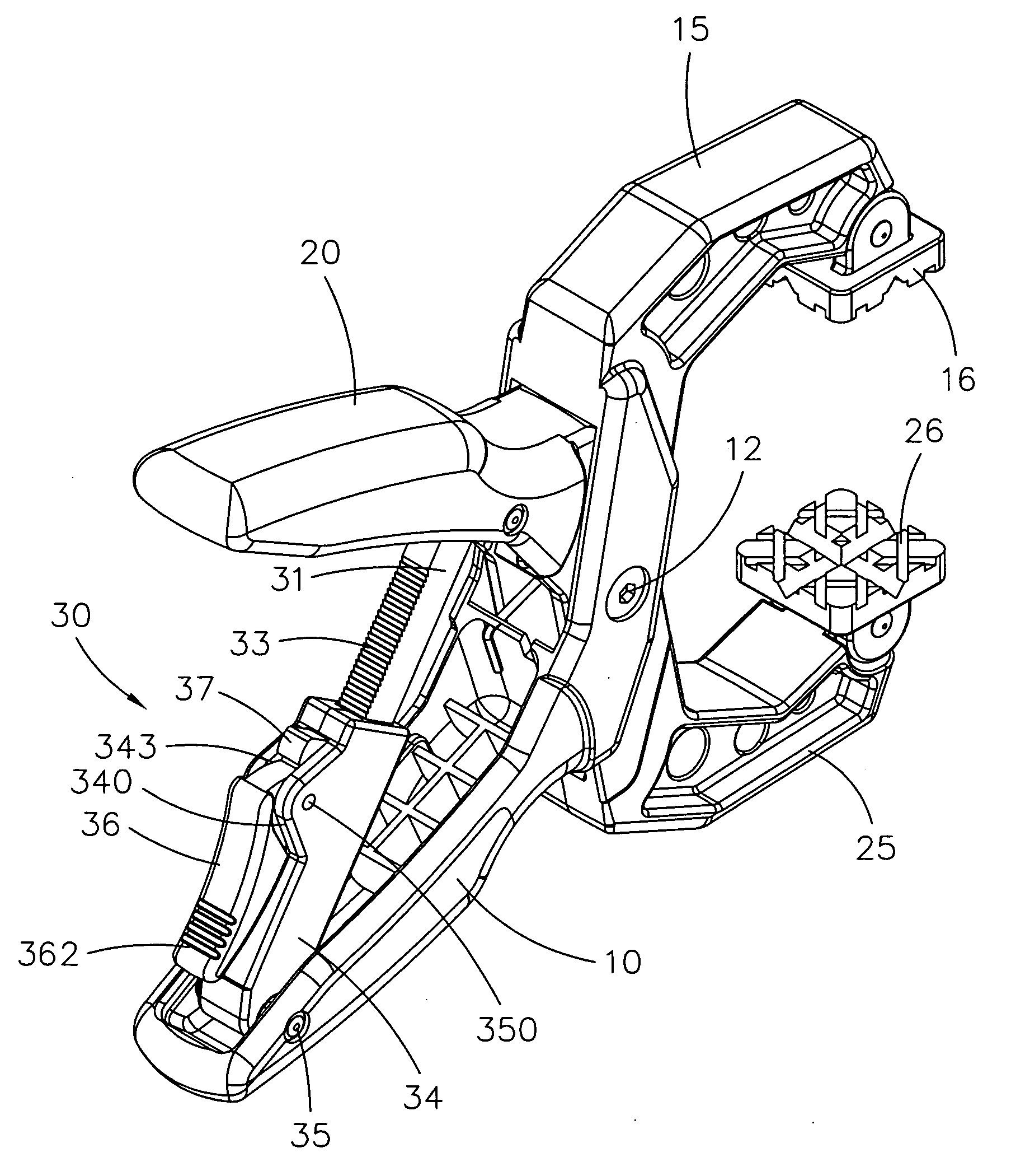
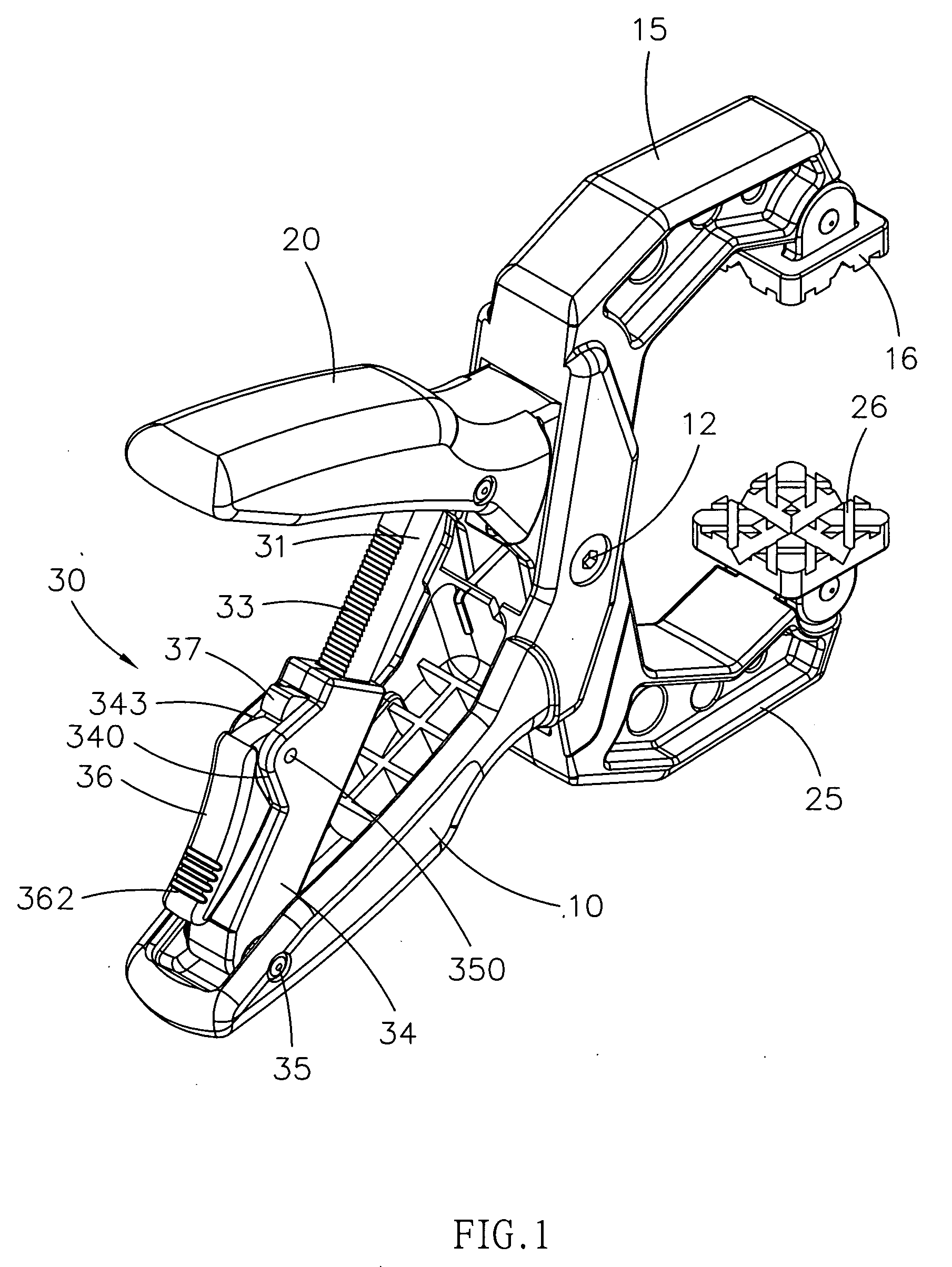
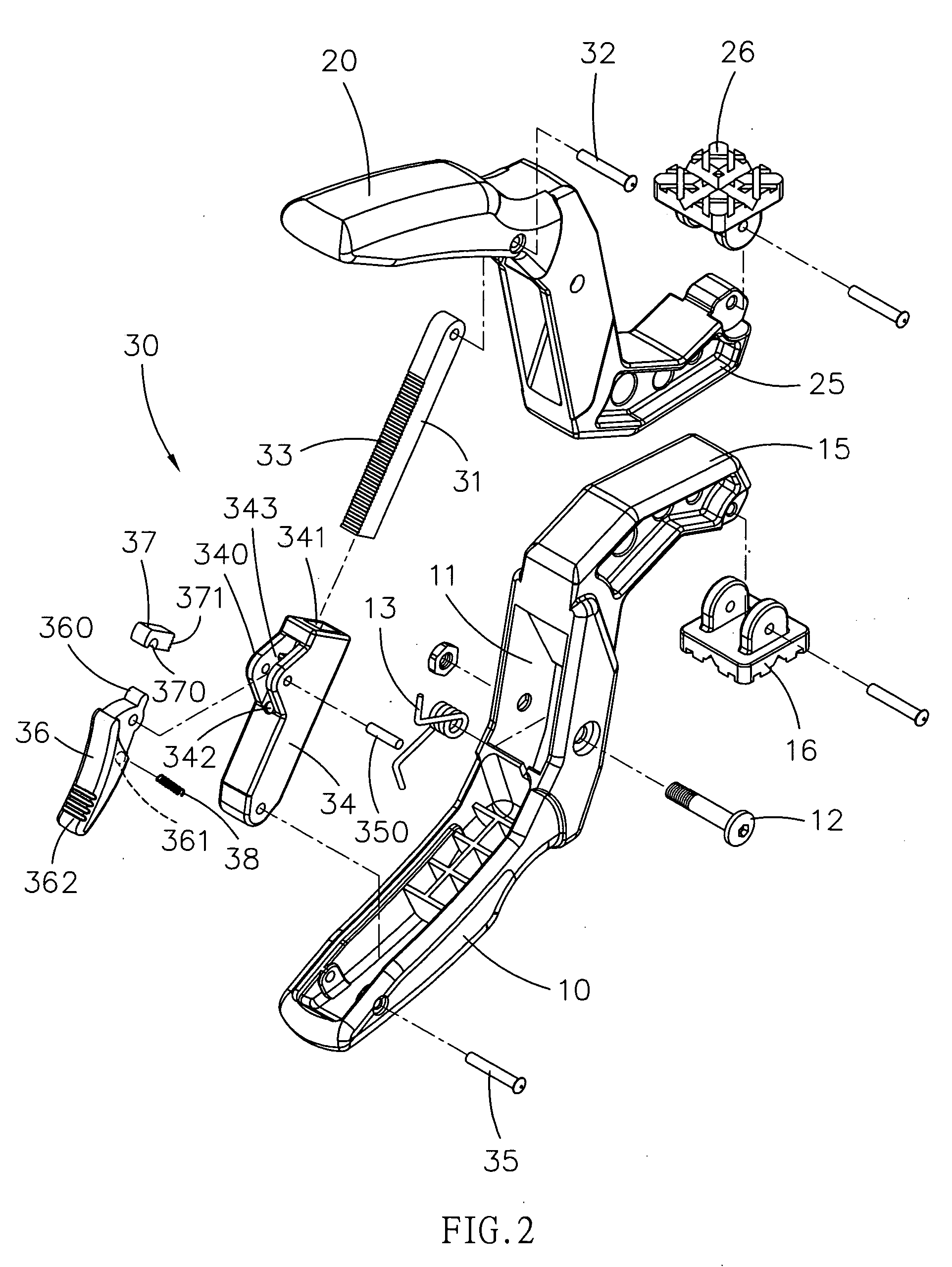
[0025] Referring to the drawings and initially to FIGS. 1-3, a clamping device in accordance with the preferred embodiment of the present invention comprises a first handle 10 having a first end formed with a first jaw 15 provided with a first clamp 16, a second handle 20 pivotally connected with the first handle 10 and having a first end formed with a second jaw 25 provided with a second clamp 26, and a positioning unit 30 mounted between a second end of the first handle 10 and a second end of the second handle 20 to control a relative angle between the first handle 10 and the second handle 20.

[0026] The first handle 10 has a mediate portion formed with a passage 11 to allow passage of the second handle 20. The second handle 20 is pivotally connected with the first handle 10 by a pivot shaft 12. A torsion spring 13 is mounted on the pivot shaft 12 and biased between the first handle 10 and the second handle 20 to open the first handle 10 and the second handle 20, so that the first...


PUM


Abstract

A clamping device includes a first handle, a second handle, and a positioning unit. The positioning unit includes a sleeve pivotally mounted on the first handle, a rack pivotally mounted on the second handle and movably mounted in the sleeve, a control member pivotally mounted on the sleeve and having a first end extended into the sleeve, and a locking member mounted on the first end of the control member to move therewith and detachably engaged with the rack to limit movement of the rack. Thus, the locking member on the sleeve is normally engaged with the rack, so that the first handle and the second handle are positioned by the positioning unit rigidly and stably, thereby facilitating a user operating the claimping device.

Description

BACKGROUND OF THE INVENTION [0001] 1. Field of the Invention [0002] The present invention relates to a clamping device, and more particularly to a clamping device for clamping a workpiece. [0003] 2. Description of the Related Art [0004] A clamping device is used for clamping a workpiece, such as a wooden plate, metallic plate, plastic plate or the like. The clamping device usually comprises two clamping handles, and a positioning unit mounted between the two clamping handles. Thus, the positioning unit can lock and position the two clamping handles in place after the two clamping handles clamp the workpiece, thereby preventing the two clamping handles from being loosened due to hit of a foreign force. [0005] A conventional clamping device in accordance with the prior art is disclosed in the Taiwanese Patent Publication No. 386480. However, when the shaft is slidable relative to the socket, the shaft easily vibrates due to a gap between the shaft and the socket, thereby causing incon...

Claims


Application Information

Patent Timeline
IPC IPC(8): B25B1/00
CPCB25B5/06B25B7/14
Inventor WANG, GUEI-YING
Owner WANG GUEI YING
Why Eureka
Try Eureka