Sand-belt finishing machine having dust clearing function

Inactive Publication Date: 2005-04-07
WANG WANG TIEN
View PDF3 Cites 14 Cited by
  • Summary
  • Abstract
  • Description
  • Claims
  • Application Information

AI Technical Summary

Benefits of technology

[0007] The present invention is to mitigate and/or obviate the

Problems solved by technology

In addition, the user needs to remove the hood 16 of the dust clearing device before replacing the sand belt 14, thereby causing inconvenience in replacement and maintenance.
Further, the sand belt 14

Method used


Image

  • Sand-belt finishing machine having dust clearing function
  • Sand-belt finishing machine having dust clearing function
  • Sand-belt finishing machine having dust clearing function

Examples


Example

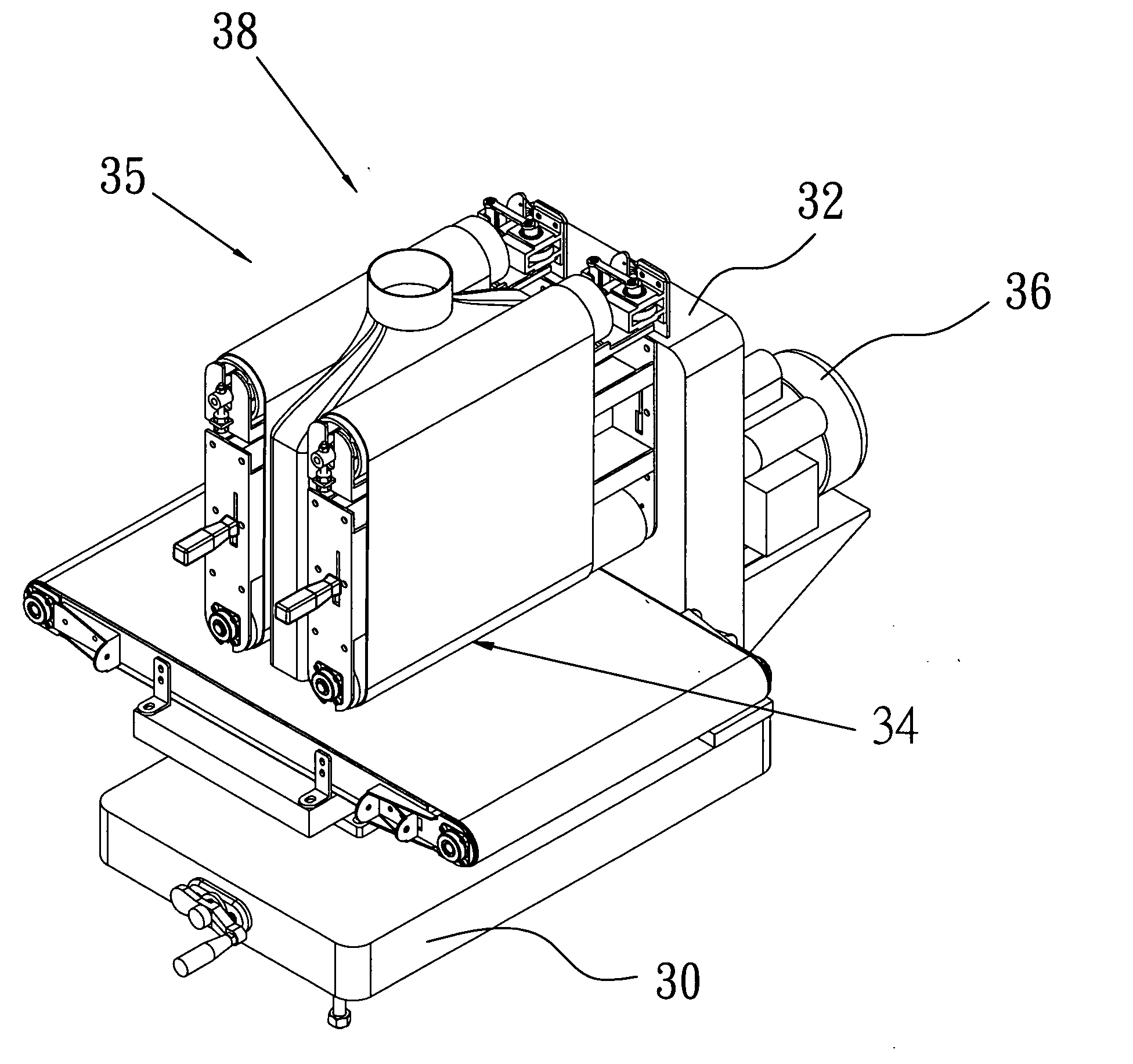
[0021] Referring to the drawings and initially to FIGS. 3 and 4, a sand-belt finishing machine in accordance with the preferred embodiment of the present invention comprises a main frame 30 disposed at a horizontal state, an upright seat 32 mounted on and vertical to the main frame 30, and two grinding devices 34 and 35 mounted on two sides of the upright seat 32.

[0022] The grinding device 34 includes two rollers 342 and 344 each located beside the upright seat 32, and a sand belt 346 reeved around the two rollers 342 and 344. The two rollers 342 and 344 of the grinding device 34 are spaced from each other and are mounted on the upright seat 32 in a parallel manner.

[0023] The grinding device 35 includes two rollers 352 and 354 each located beside the upright seat 32, and a sand belt 356 reeved around the two rollers 352 and 354. The two rollers 352 and 354 of the grinding device 35 are spaced from each other and are mounted on the upright seat 32 in a parallel manner.

[0024] Prefe...


PUM


Abstract

A sand-belt finishing machine includes two opposite grinding devices arranged in parallel with each other and each including two opposite rollers and a sand belt reeved around the two rollers, and a dust clearing device mounted between the two grinding devices. Thus, the wooden board is placed on a single main frame and is processed by a single working procedure to synchronously obtain a double surface treatment, including the rough working treatment and the finishing treatment, thereby greatly simplifying the working process.

Description

BACKGROUND OF THE INVENTION [0001] 1. Field of the Invention [0002] The present invention relates to a sand-belt finishing machine having a dust clearing function, and more particularly to a sand-belt finishing machine that is processed by a single working procedure to synchronously obtain a double surface treatment, including the rough working treatment and the finishing treatment, thereby simplifying the working process. [0003] 2. Description of the Related Art [0004] A conventional sand-belt finishing machine in accordance with the prior art shown in FIG. 1 comprises two rollers 12, a sand belt 14 reeved around the two rollers 12, and a dust clearing device including a hood 16 mounted outside of the two rollers 12 and the sand belt 14, and a suction member 18 mounted on the hood 16. Thus, the chips produced from the wooden board 50 during the grinding process can be introduced into the hood 16 by the suction effect of the suction member 18 and can then be drained outward. [0005] ...

Claims


Application Information

Patent Timeline
IPC IPC(8): B24B21/00B24B21/04B24B55/08
CPCB24B21/008B24B55/08B24B21/04
Inventor WANG, WANG TIEN
Owner WANG WANG TIEN
Why Eureka
Try Eureka