Ratchet wrench structure

Active Publication Date: 2005-06-07
CHEN YU TANG
View PDF6 Cites 12 Cited by
  • Summary
  • Abstract
  • Description
  • Claims
  • Application Information

AI Technical Summary

Benefits of technology

[0007]The present invention is to mitigate and/or obviate th

Problems solved by technology

However, the conventional ratchet wrench structure is only available for the socket 61A with arcuate insertion recesses 610A shown in FIG. 8, and is not available for the socket 60A with sector-shaped insertion recesses 600A sh

Method used


Image

  • Ratchet wrench structure
  • Ratchet wrench structure
  • Ratchet wrench structure

Examples


Embodiment Construction

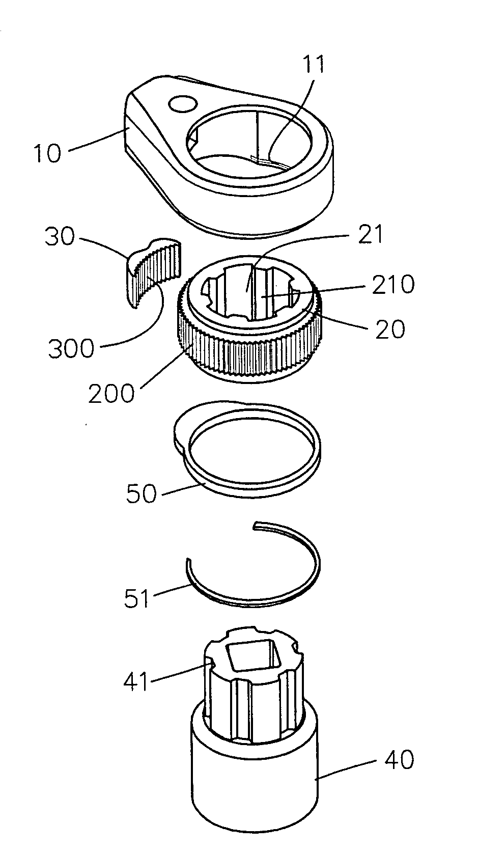
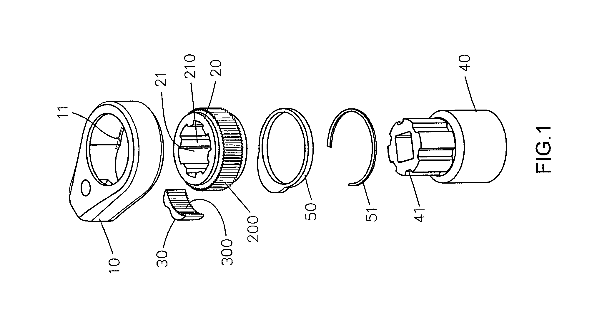
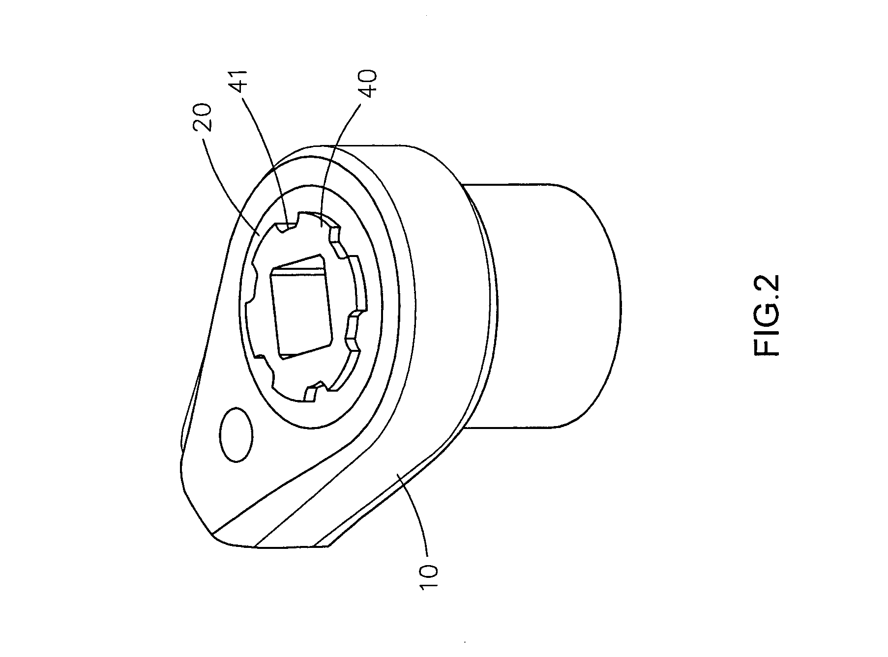
[0032]Referring to the drawings and initially to FIGS. 1–3, a ratchet wrench structure in accordance with the preferred embodiment of the present invention comprises a wrench body 10, a ratchet wheel 20, and a socket 40.

[0033]The wrench body 10 has a head formed with a receiving hole 11.

[0034]The ratchet wheel 20 is rotatably mounted in the receiving hole 11 of the wrench body 10. The ratchet wheel 20 has an outer wall formed with a plurality of ratchet teeth 200. The ratchet wheel 20 has a center formed with a combination hole 21. The combination hole 21 of the ratchet wheel 20 has an inner periphery formed with a plurality of insertion ribs 210.

[0035]As shown in FIG. 3A, each of the insertion ribs 210 of the ratchet wheel 20 includes two first insertion faces 211 located on the two opposite sides thereof, and a second insertion face 212 located between the two first insertion faces 211. Preferably, each of the two first insertion faces 211 of each of the insertion ribs 210 has an ...


PUM


Abstract

A ratchet wrench structure includes a wrench body, a ratchet wheel, and a socket. The ratchet wheel has a center formed with a combination hole which has an inner periphery formed with a plurality of insertion ribs. Each of the insertion ribs of the ratchet wheel includes two first insertion faces located on the two opposite sides thereof, and a second insertion face located between the two first insertion faces. Thus, the ratchet wrench structure is available for sockets with sector-shaped and arcuate-shaped insertion recesses.

Description

BACKGROUND OF THE INVENTION[0001]1. Field of the Invention[0002]The present invention relates to a ratchet wrench structure, and more particularly to a ratchet wrench structure that is both available for sockets with sector-shaped and arcuate-shaped insertion recesses.[0003]2. Description of the Related Art[0004]A first conventional ratchet wrench structure in accordance with the prior art shown in FIG. 8 comprises a wrench body 10A, a ratchet wheel 12A rotatably mounted in the wrench body 10A and having an inner wall formed with a plurality of arcuate insertion ribs 120A, and a socket 61A mounted in the ratchet wheel 12A and having an outer periphery formed with a plurality of arcuate insertion recesses 610A for insertion of the insertion ribs 120A of the ratchet wheel 12A. Thus, the socket 61A is combined with the ratchet wheel 12A, so that the socket 61A can co-operate with the ratchet wheel 12A to rotate a screw member (not shown) by rotation of the wrench body 10A. However, the...

Claims


Application Information

Patent Timeline
IPC IPC(8): B25B13/00B25B13/46B25B23/00
CPCB25B23/0035B25B13/463
Inventor CHEN, YU TANG
Owner CHEN YU TANG
Why Eureka
Try Eureka