
Portable heat exchanging device

a heat exchange device and portable technology, applied in the field of portable heat exchange devices, can solve the problems of increasing fabrication costs and sanitary problems, and achieve the effect of reducing disadvantages and/or obviating disadvantages

Inactive Publication Date: 2006-05-30
LIN AMOS
View PDF12 Cites 13 Cited by
  • Summary
  • Abstract
  • Description
  • Claims
  • Application Information

AI Technical Summary

Benefits of technology

[0006]The present invention is to mitigate and / or obviate the disadvantage of the conventional heat exchanging device.
[0007]The primary objective of the present invention is to provide a heat exchanging device that is received in the receiving portion of the cover to perform the heat exchanging action with the inside of the cover, so that the cover will not touch the food contained in the container, thereby achieving the sanitary purpose.
[0008]Another objective of the present invention is to provide a heat exchanging device that can be detached from the cover and the container, so that the heat exchanging device can be replaced easily and conveniently when being inoperative without having to move the food, thereby facilitating the user using the heat exchanging device, and thereby achieving the sanitary purpose.
[0009]A further objective of the present invention is to provide a heat exchanging device that is mounted in the closed space formed by the cover and the container to form a closed heat exchanging space, so that the food is entirely received in closed heat exchanging space, thereby enhancing the heat exchanging efficiency of the heat exchanging device.
[0010]A further objective of the present invention is to provide a heat exchanging device, wherein the combination portion of the primary body can be directly mounted on the stand portion of the container, so that the heat exchanging device can be used independently, thereby greatly facilitating the user using the heat exchanging device.

Problems solved by technology

Further, the heat exchanging device 91 easily touches the food located above the baffle 92, thereby incurring a sanitary problem.
Further, it is necessary to form the receiving recess 900 in the dish 90 for receiving the heat exchanging device 91, thereby increasing costs of fabrication.

Method used


Image

  • Portable heat exchanging device
  • Portable heat exchanging device
  • Portable heat exchanging device

Examples


Embodiment Construction

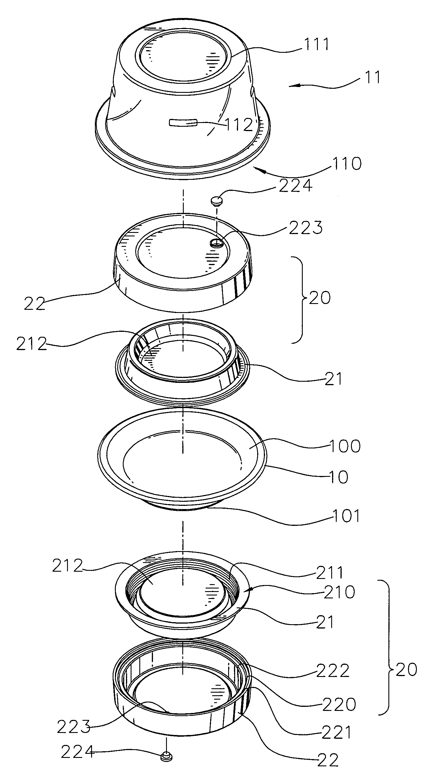
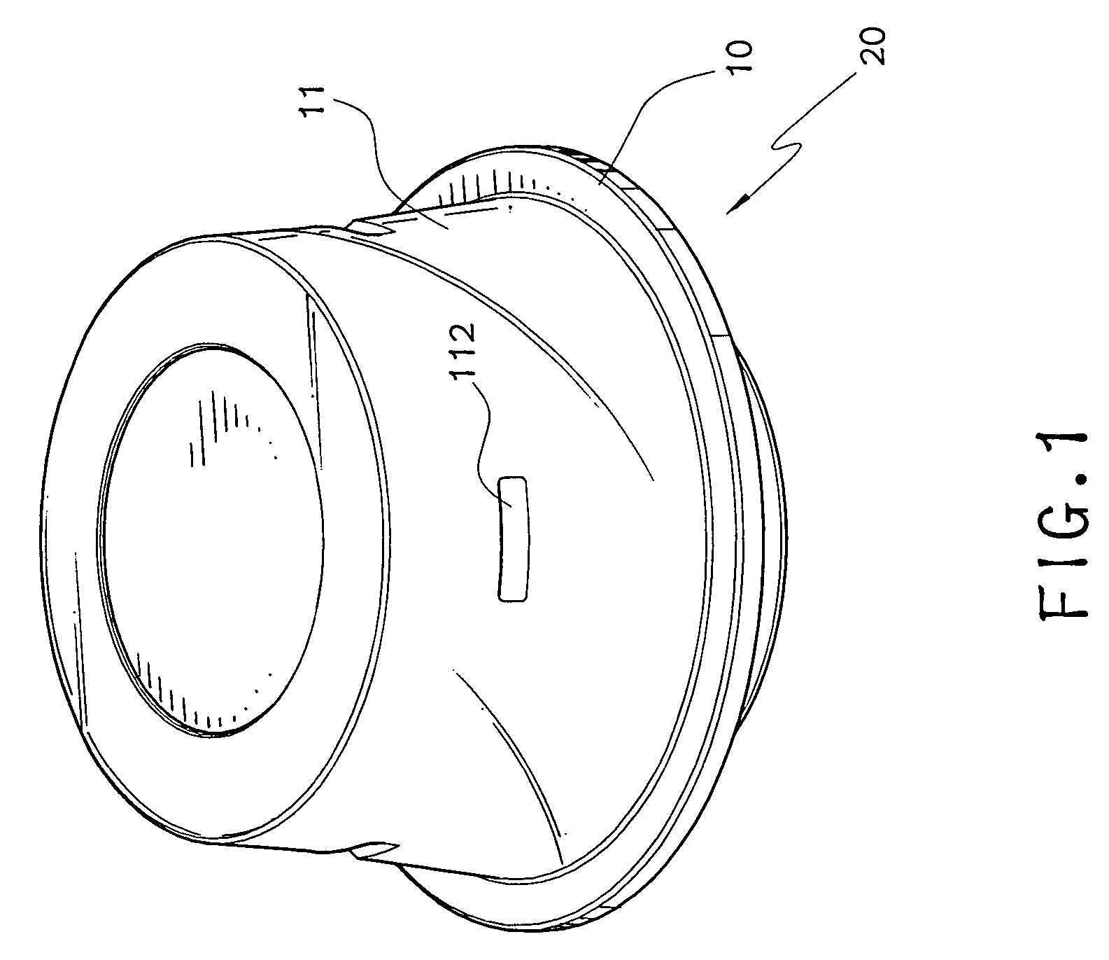
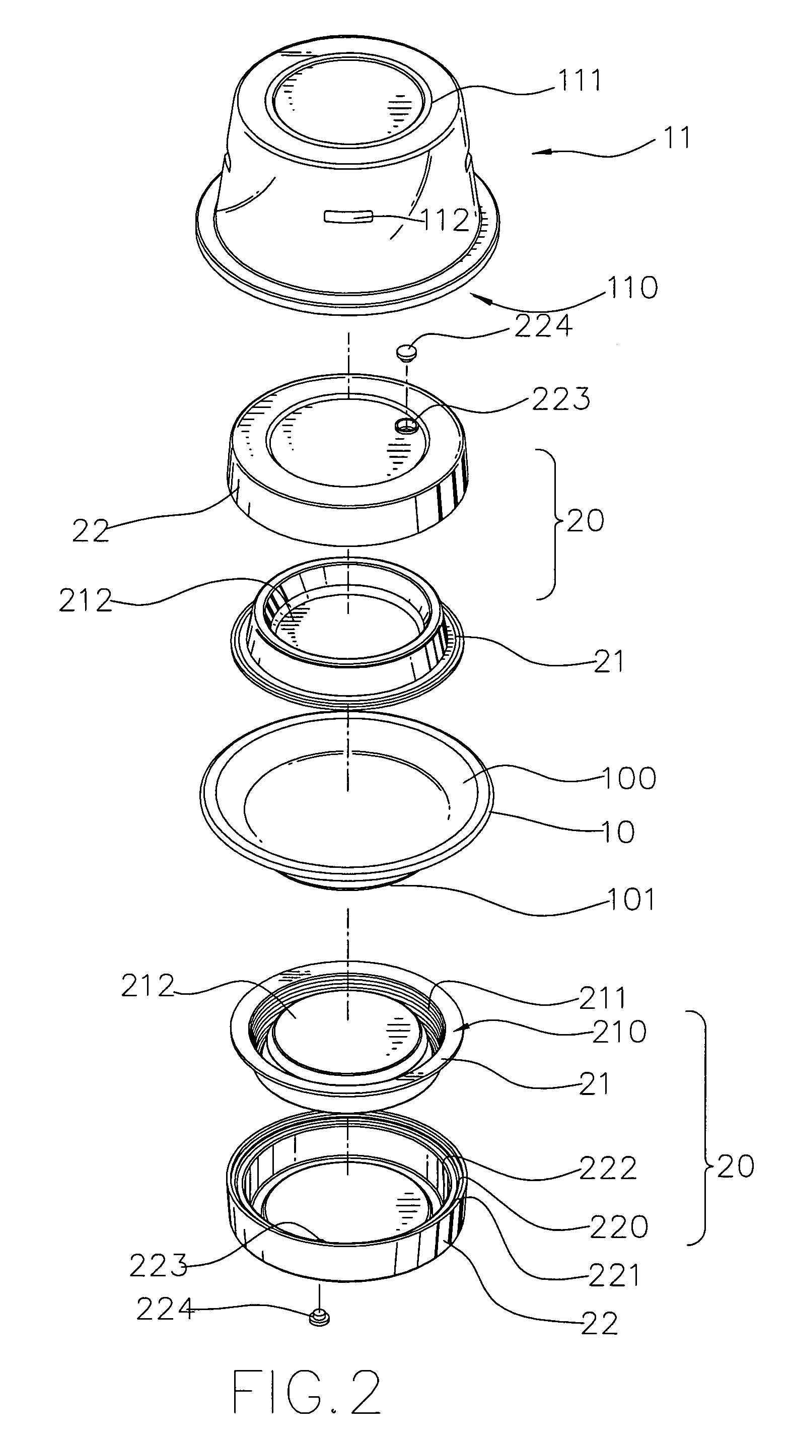
[0020]Referring to the drawings and initially to FIGS. 1–3, a portable heat exchanging device 20 in accordance with the preferred embodiment of the present invention is mounted on a container 10 or a cover 11.

[0021]The container 10 contains a food therein and has a top formed with a support portion 100 and a bottom provided with a stand portion 101.

[0022]The cover 11 is mounted on the container 10 and has a bottom formed with a receiving portion 110 for receiving the top of the container 10.

[0023]The heat exchanging device 20 is detachably mounted on the stand portion 101 of the container 10 or detachably mounted in the receiving portion 110 of the cover 11.

[0024]The heat exchanging device 20 comprises a primary body 21 and a secondary body 22 mounted on the primary body 21.

[0025]The primary body 21 has a disk shape, and has a periphery formed with a recessed combination portion 210 mounted on the stand portion 101 of the container 10. The combination portion 210 of the primary body...


PUM


Abstract

A heat exchanging device is detachably mounted on a container or a cover. The cover is mounted on the container, thereby forming a closed space between the cover and the container. The heat exchanging device containing a temperature regulating medium is mounted in the closed space between the cover and the container. Thus, the heat exchanging device can be replaced easily and conveniently when being inoperative without having to move the food, thereby facilitating the user using the heat exchanging device, and thereby achieving the sanitary purpose.

Description

BACKGROUND OF THE INVENTION[0001]1. Field of the Invention[0002]The present invention relates to a portable heat exchanging device, and more particularly to a portable heat exchanging device that can be replaced easily and has an enhanced heat exchanging efficiency.[0003]2. Description of the Related Art[0004]A conventional heat exchanging device 91 in accordance with the prior art shown in FIG. 5 is mounted in a receiving recess 900 of a dish 90 which is covered by a cover 93. The receiving recess 900 of the dish 90 has a top provided with a baffle 92 to cover the heat exchanging device 91.[0005]However, the heat exchanging device 91 is hidden in the receiving recess 900 of the dish 90 to perform the heat exchanging action with the food located above the baffle 92, thereby decreasing heat exchanging efficiency of the heat exchanging device 91. In addition, the heat exchanging device 91 is hidden in the receiving recess 900 of the dish 90, so that the user needs to remove the cover ...

Claims


Application Information

Patent Timeline
Patent Type & Authority Patents(United States)
IPC IPC(8): A47G23/04A47J36/24A47J39/02A47J41/00
CPCA47J41/0044A47J36/24
Inventor LIN, AMOS
Owner LIN AMOS
Learn More