Spring detachment device for automobile

Inactive Publication Date: 2005-03-29
LIU TONY
View PDF2 Cites 14 Cited by
  • Summary
  • Abstract
  • Description
  • Claims
  • Application Information

AI Technical Summary

Benefits of technology

The present invention is to mitigate and/or obviate the d

Problems solved by technology

However, the conventional spring detachment device needs to be operated by at least two persons, thereby wasting the manual work and the working time during operation.
In addition, the inclined operatio

Method used


Image

  • Spring detachment device for automobile
  • Spring detachment device for automobile
  • Spring detachment device for automobile

Examples


Embodiment Construction

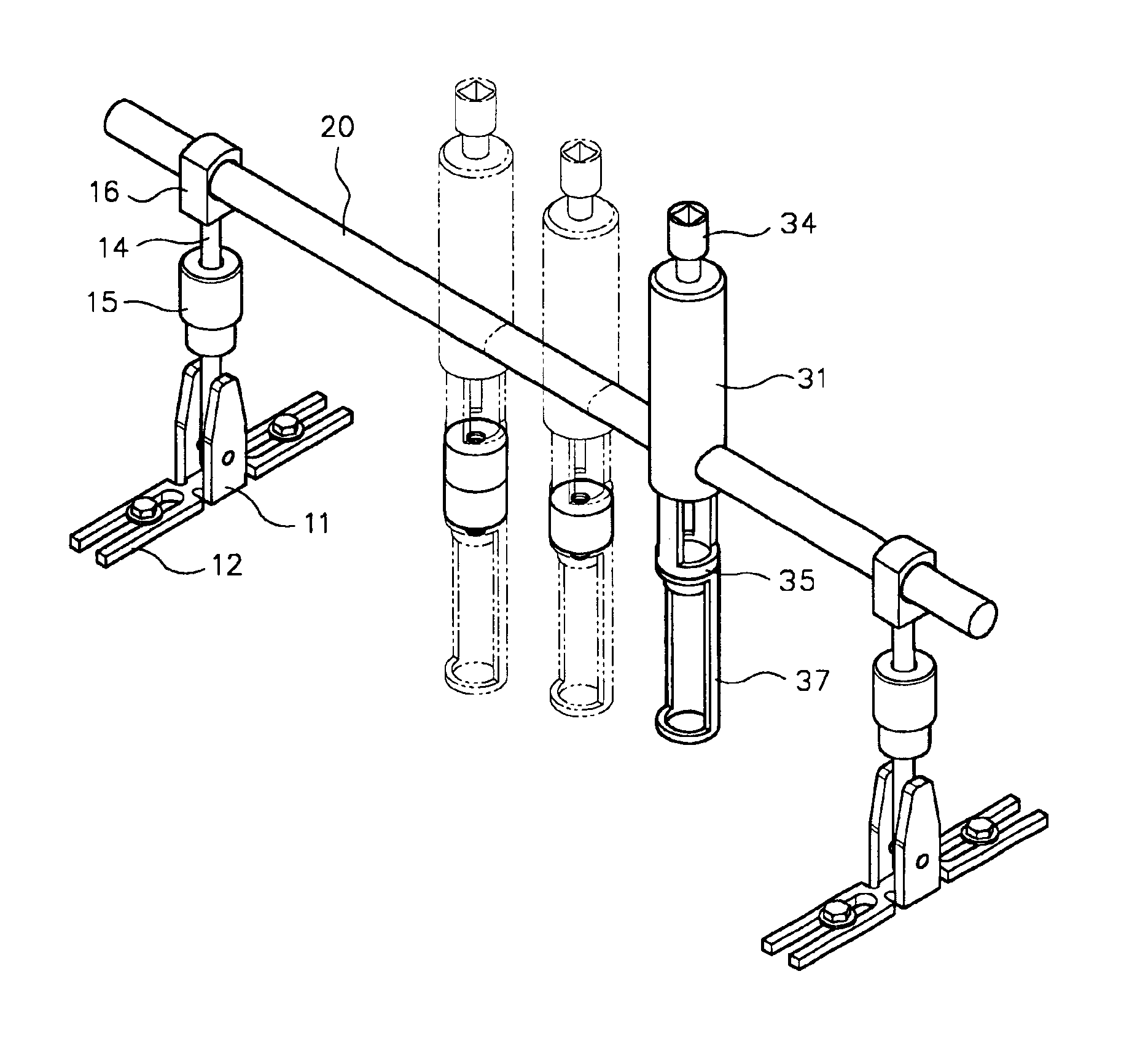
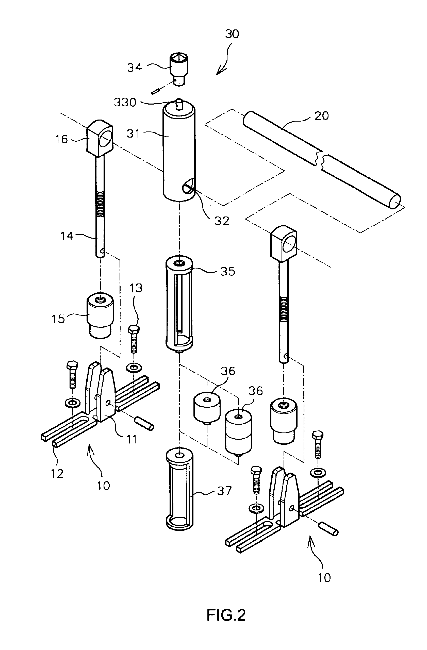
Referring to the drawings and initially to FIGS. 2-7, a spring detachment device for an automobile in accordance with the preferred embodiment of the present invention comprises two fixing seats 10, a transverse rod 20, and an operation mechanism 30.

Each of the two fixing seats 10 includes an U-shaped base 11, a support rack 12 mounted on and protruded outward from the base 11, a threaded rod 14 having a lower end pivotally mounted on the base 11 and an upper end provided with a support block 16, an adjusting block 15 movably mounted on the threaded rod 14 and rested on a top of the base 11 to adjust an inclined angle of the threaded rod 14. In addition, the support rack 12 of each of the two fixing seats 10 is fixed on an end face of the engine 40 (see FIG. 5) of the automobile by two screw members 13.

The transverse rod 20 is mounted between the two fixing seats 10 and has two ends each extended through the support block 16 of a respective one of the two fixing seats 10.

The operati...


PUM

PropertyMeasurementUnit
Angleaaaaaaaaaa
Distanceaaaaaaaaaa

Abstract

A spring detachment device includes two fixing seats, a transverse rod, and an operation mechanism. Thus, the spring detachment device can be operated by a single person only, thereby saving the manual work and the working time. In addition, the distance between the operation mechanism and the air door can be adjusted easily and conveniently, thereby facilitating the user replacing the spring.

Description

BACKGROUND OF THE INVENTION1. Field of the InventionThe present invention relates to a spring detachment device, and more particularly to a spring detachment device for detaching the spring of one of the air doors of an automobile.2. Description of the Related ArtA conventional spring detachment device in accordance with the prior art shown in FIG. 1 comprises two fixing seats 1, a transverse rod 2 mounted between the two fixing seats 1, an operation rod 4 mounted on the transverse rod 2, and an operation wrench 3 mounted on the operation rod 4. Thus, the conventional spring detachment device is used for detaching the spring (not shown) of one of the air doors (not shown) of an automobile.However, the conventional spring detachment device needs to be operated by at least two persons, thereby wasting the manual work and the working time during operation. In addition, the inclined operation angle of the conventional spring detachment device is limited, so that the conventional spring ...

Claims


Application Information

Patent Timeline
IPC IPC(8): B23P19/04B25B27/00B25B27/30
CPCB23P19/048B25B27/0035B25B27/304B25B27/26Y10T29/5357
Inventor LIU, TONY
Owner LIU TONY
Why Eureka
Try Eureka