Percutaneous needle alignment system and associated method

a technology of alignment system and percutaneous needle, which is applied in the field of trajectory system for medical instruments, can solve the problems of limited options for mentors or teachers, unfavorable listening of awake patients, and difficulty in obtaining the requisite skill of newcomers (or less experienced clinicians)

Inactive Publication Date: 2003-08-12
WARSAW ORTHOPEDIC INC
View PDF21 Cites 70 Cited by
  • Summary
  • Abstract
  • Description
  • Claims
  • Application Information

AI Technical Summary

Benefits of technology

The present invention can further comprise a needle driver for supporting the length of the needle in a proper trajectory. The needle driver is designed to prevent bending of the needle. In such an embodiment, the energy source can be communicative with the driver, instead of the needle, and the driver properly aligned as previously discussed. Once the driver trajectory is equivalent with the injection trajectory, the needle can be passed through the needle driver, and the injection be assured of alignment. Alternatively, the needle driver can itself be advanced percutaneously in some insertion techniques.
The present invention need not necessarily be used with fluoroscopy, but can also be used as a teaching tool for lumbar punctures and other biopsy procedures. The lumbar puncture is often performed by third-year medical students and is based on known anatomy. With the present invention, the correct trajectory can be presented to the student by having a light on the end of the needle and watching and using this light as a reference point. For example, if a supervising physician in the room is aware of the correct trajectory based on his / her experience and knowledge and is trying to convey this to the medical student performing the injection of a needle, the present invention is a nice teaching tool to convey to the medical student the correct trajectory for insertion. Rather than using terms of "move the needle tip" or "move the needle hub right, left, up or down", the supervising physician can simply take hold of the needle without advancing it, and show the medical student the correct trajectory without advancing the needle and the medical student can take notice of where the light, which is added to the hub of the spinal needle, appears relative to a reference point within the room. In this way the medical student can pass the needle as the supervising physician intended the medical student to do by assuring that the student's light path shines upon the mark indicated by the supervisor.

Problems solved by technology

While skilled clinicians may perform the insertion satisfactorily, a novice (or less experienced clinician) has difficulty obtaining the requisite skill.
In such settings, there are limited options for the mentor or teacher to convey to the trainee just what the intended trajectory should be based on the years of experience of the mentor.
The mentor often is reluctant to "talk" the trainee through the procedure, as this can make the awake patient who is listening quite uncomfortable.
Yet, this lack of oral communication often results in a miscalculated pass of the spinal needle by the trainee.
The disadvantages of this type of needle guidance are apparent and well understood both by those in the art and those unfortunate patients that require repeated insertions with misguided needle insertions.
The inability of the clinician to ensure, in real-time, the correct trajectory of the needle from the insertion site to the target site may cause significant patient discomfort.
However, these devices are not very efficient.
Repositioning the C-arm repeatedly in response to patient movement can be so time consuming as to render the McNeirney et al. system impractical.
Another problem that can arise with free-hand needle insertion primarily is due to the flexibility inherent in puncture needles in view of a needle's small diameter relative to its length.
This leaves the length of the needle unsupported, thus facilitating needle deflection under the insertion force of the clinician's fingers.
Injection procedures also suffer from the problem of insufficient needle point friction control at the insertion site on the skin when beginning the insertion procedure.
Thus, repeatable on-phase insertions can not be guaranteed even with the same clinician.
Yet, if too little contact is brought against the skin and proximal end of the needle, the needle point can float above the insertion site, making the alignment procedure more difficult.
However, with prior art trajectory systems that utilize light shone on the patient to identify the insertion site, if the patient subsequently moves, then the C-arm and attending machinery must be realigned.
This can be quite a common problem, since the patients are rarely heavily sedated to such an extent that they do not move.
Additionally prior art devices are very expensive, cumbersome and are not cost effective or time efficient.
Further, prior art guidance devices provide the clinician only two discrete settings, on or off alignment.
Parallax may cause the image visualized on the x-ray machine not to be actually representative of space and the target area.
With prior art devices, it is too time consuming to continually take fluoroscopic pictures until the anatomic structure of interest is in the center of the screen.

Method used


Image

  • Percutaneous needle alignment system and associated method
  • Percutaneous needle alignment system and associated method
  • Percutaneous needle alignment system and associated method

Examples


Embodiment Construction

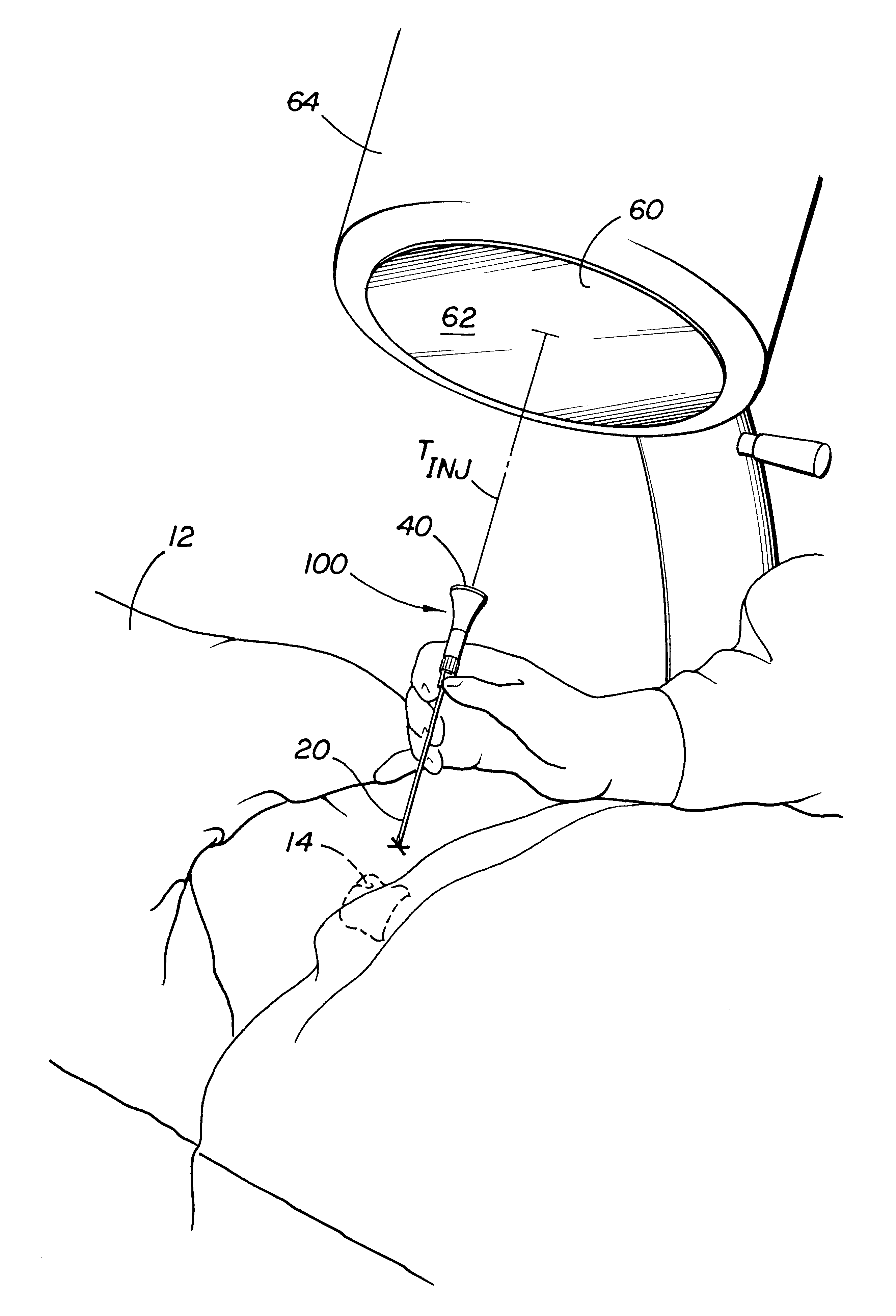
Referring now in detail to the drawing figures, wherein like reference numerals represent like parts throughout the several views, FIG. 1 illustrates the present alignment system 100 comprising a insertion device 20, an energy source 40 and a reflecting element 60. The alignment system 100 is located in an injection trajectory T.sub.INJ aligning an insertion site X on the skin of a patient 12, and a target site 14 below the skin.

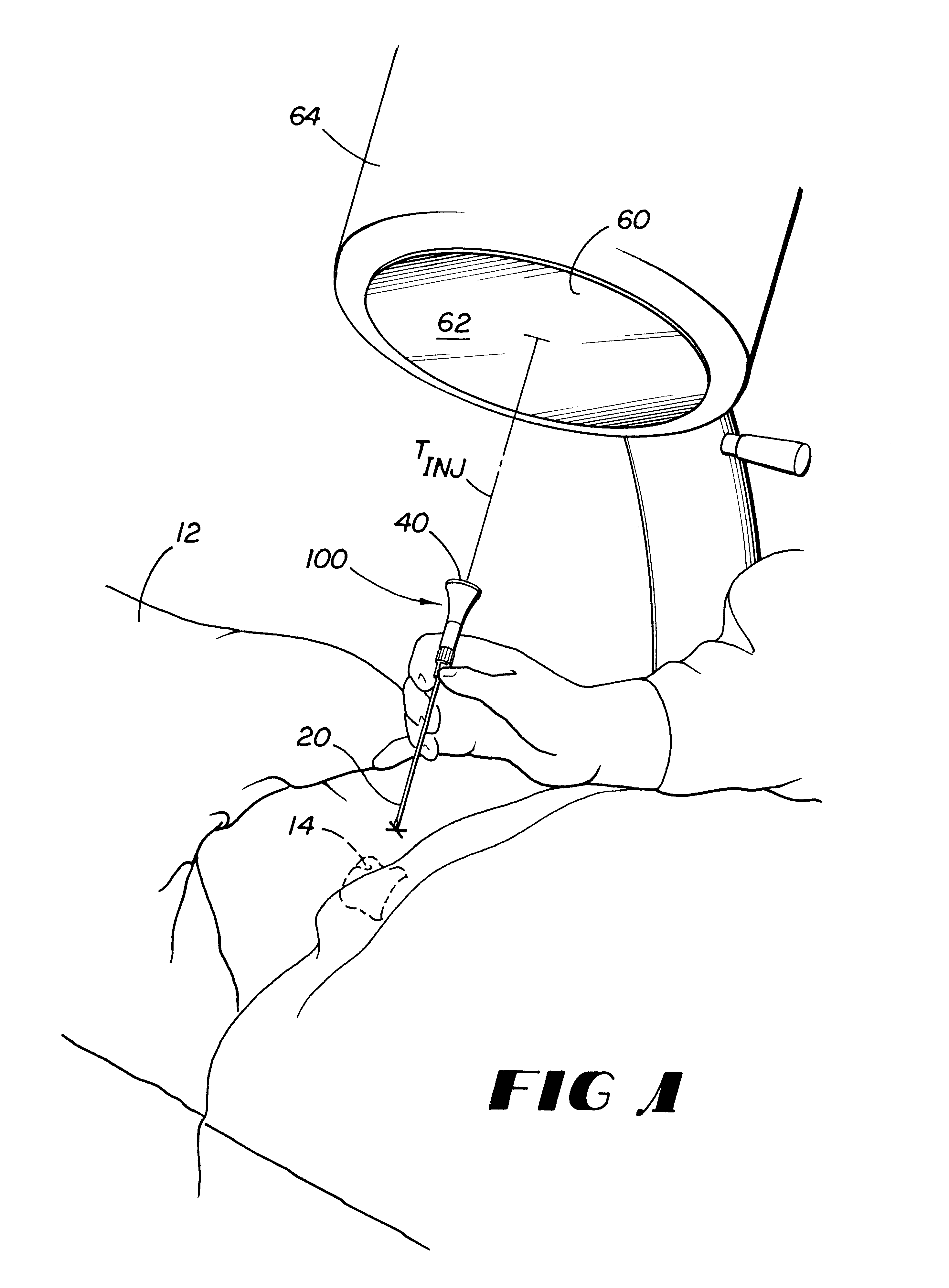
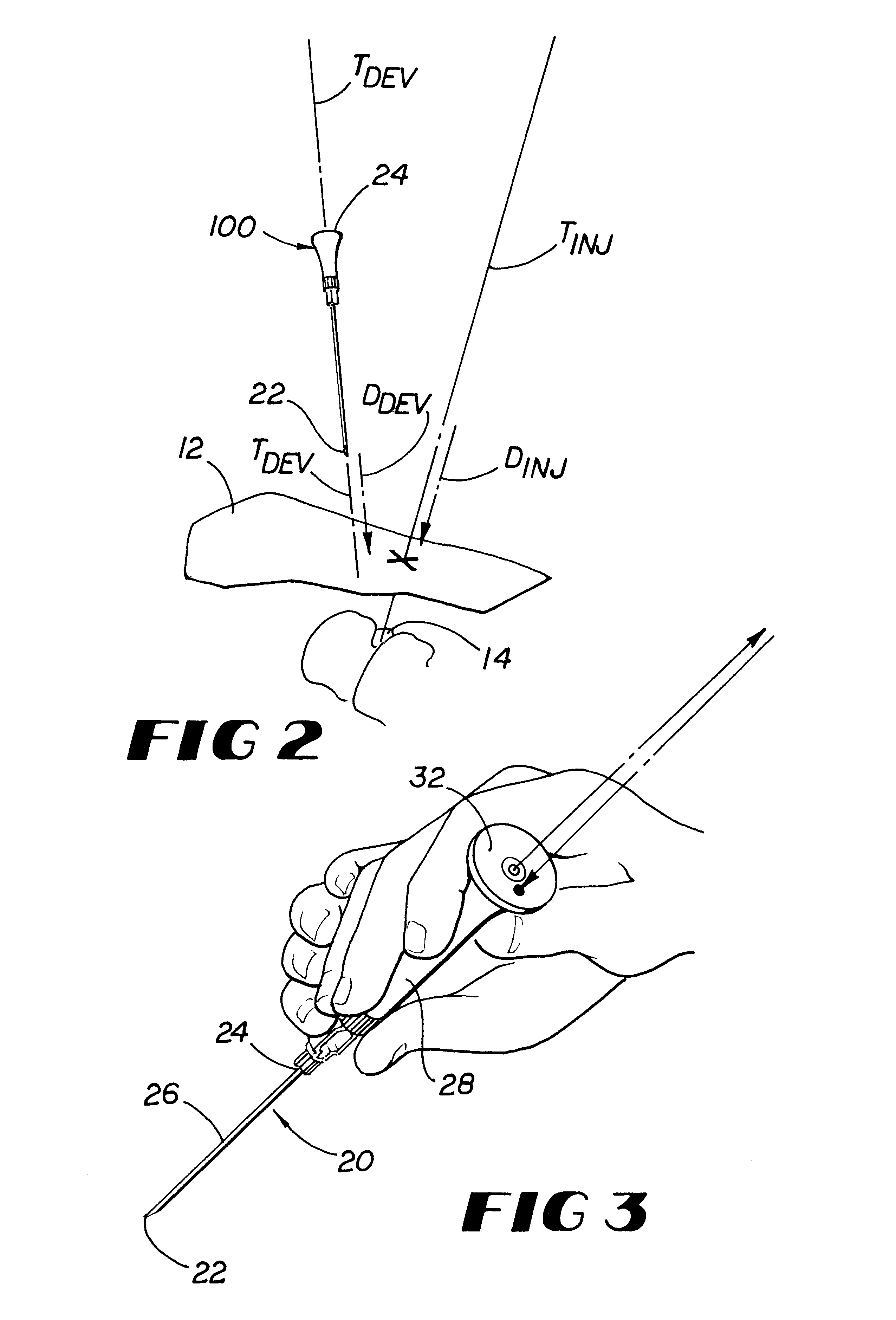
As shown in FIG. 2 and as used herein, the term "injection trajectory" T.sub.INJ is defined as the trajectory passing through the insertion site X on the skin and the target site 14 within the body, and the term "injection direction" D.sub.INJ is defined as the direction lying on the injection trajectory T.sub.INJ from the insertion site X to the target site 14.

As distinguished from the injection trajectory T.sub.INJ and the injection direction D.sub.INJ, the insertion device 20 has a device trajectory T.sub.DEV (or sometimes needle trajectory) and a device ...


PUM


Abstract

The present invention is an alignment system by which a needle or other similar invasive device can be positioned for insertion so as to have a real-time, predetermined trajectory to a targeted tissue region, thereby reducing the need for repetitive needle insertion and withdrawal to move the tip of the instrument accurately to the target site.

Description

1. Field of the InventionThe present invention generally relates to a trajectory system for medical instruments, and more particularly to a light-guided alignment system for a percutaneous needle.2. Description of Related ArtGuidance methods are often used in conjunction with various injection procedures. The most common guidance method for inserting surgical instruments such as puncturing needles through the skin and to a subsurface injection site is simply reliance on the clinician's experience in visualizing a proper injection trajectory, and then maintaining that trajectory throughout insertion.One type of injection procedure is the spinal injection, performed most often by a pain management specialist in which a mixture of steroid and anesthetic is delivered to specific internal structures of the body including, but not limited to, (i) a facet joint, (ii) an area surrounding a spinal nerve root, (iii) a major articulation, for example, a sacro iliac joint, and (iv) a vertebral ...

Claims


Application Information

Patent Timeline
Patent Type & Authority Patents(United States)
IPC IPC(8): A61B19/00A61M5/178
CPCA61B19/201A61B17/3403A61B19/5244A61B2017/3407A61B2019/202A61B2019/5238A61B2019/5445A61B90/13A61B2090/3945A61B2090/376A61B90/11A61B34/20
Inventor GROSSMAN, JEFFREY
Owner WARSAW ORTHOPEDIC INC
Why Eureka
Try Eureka