
Laminate for reducing flow resistance and manufacturing method therefor

a technology of reducing flow resistance and manufacturing method, which is applied in the direction of lubricant composition, mechanical equipment, coatings, etc., can solve the problems of environmental pollution, difficult to apply the same to a large area, and microbial adhesion, and achieves excellent effect, small shear force, and superior cleaning effect.

Active Publication Date: 2020-08-18
PUSAN NAT UNIV IND UNIV COOPERATION FOUND
View PDF12 Cites 0 Cited by
  • Summary
  • Abstract
  • Description
  • Claims
  • Application Information

AI Technical Summary

Benefits of technology

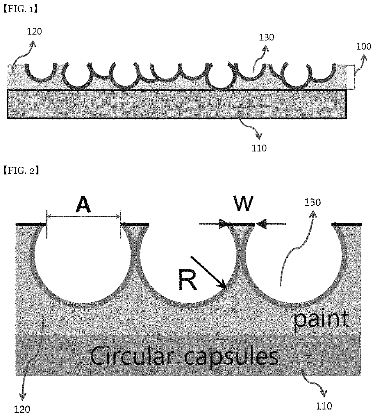
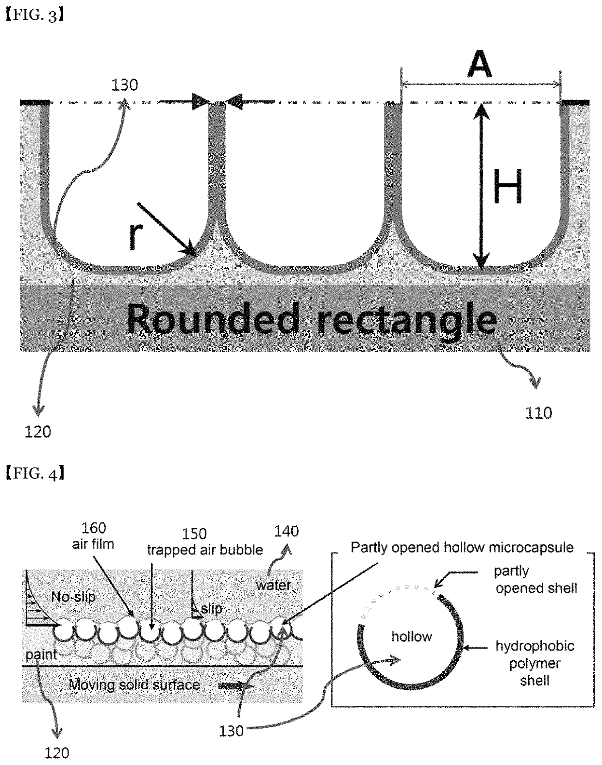
[0010]The present inventors have developed the present invention based on the fact that before the penguins enter the water, they sufficiently fill the air between feathers on the land. The effect of the penguin's air layer on frictional resistance reduction may be confirmed by comparing the flow velocity distribution and shear force based on the presence or absence of an air layer in the object surface portion. In the absence of an air layer in the surface portion, the velocity gradient is large and, thus, a large shear force is generated, while, when there is an air layer in the surface portion, a strong slip occurs on the surface of the air layer, so that the velocity gradient is small and, thus, a small shear force is obtained. As a result, the air layer plays a role in greatly reducing the flow friction resistance.
[0034]According to the present invention, when an object contacts a fluid, an air layer is formed on the surface portion of the object, and this air layer generates a strong slip, whereby the velocity gradient is small and a small shear force is realized. In this way, a near-zero flow friction resistance can be provided.

Problems solved by technology

However, since it requires precise processing of less than 200 microns, it is difficult to apply the same to a large area, and there is a problem of including microbial adhesion.
However, since the polymer must be continuously sprayed on the surface, there is a problem of environmental pollution.
However, in the case of ships, there are problems such as loss of buoyancy and propulsion, generation of cavities due to bubbles, mounting of actuators for compressed air injection, and so on.
Thus, these techniques have not been commercialized to date.

Method used


Image

  • Laminate for reducing flow resistance and manufacturing method therefor
  • Laminate for reducing flow resistance and manufacturing method therefor
  • Laminate for reducing flow resistance and manufacturing method therefor

Examples


example 1

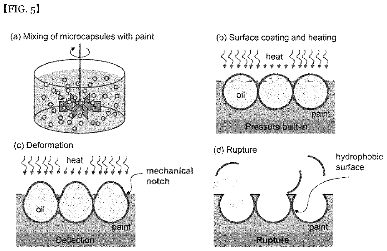
[0054]The oil-contained micro-capsule and PVA (polyvinyl alcohol) were dispersed at a ratio of 1:1. The micro-capsules were well dispersed in the PVA. This capsule-dispersed PVA was spin-coated onto the silicon surface. The specific gravity of the oil was smaller than the specific gravity of the PVA, so that the micro-capsule floated toward the PVA surface, and the PVA was cured after a certain time. See the SEM picture of FIG. 6. As shown in the SEM photograph of FIG. 7, the shell of the micro-capsule was ruptured and a surface portion of the PVA having the partially opened micro-cavities was formed.


PUM

PropertyMeasurementUnit
flow-resistanceaaaaaaaaaa
cylindrical shapeaaaaaaaaaa
thermal expansionaaaaaaaaaa

Abstract

There is provided a flow-resistance reducing laminate comprising: a substrate; and a flow-resistance reducing layer formed on the substrate, wherein the flow-resistance reducing layer has a surface portion facing a liquid, wherein a flow interface is formed between the liquid and the laminate upon relative movement between the liquid and the laminate, wherein the flow-resistance reducing layer is configured such that an air layer defines the flow interface.

Description

[0001]This application is a national phase under 35 U.S.C. § 371 of International Application No. PCT / KR2016 / 003482, filed Apr. 5, 2016, which claims the benefit of priority to Korean Patent Application Serial No. KR 10-2015-0049858, filed Apr. 8, 2015. The entire contents of each of the above-referenced applications are incorporated into the present application by reference.BACKGROUNDField of the Present Disclosure[0002]The present invention relates to a surface structure of an object for reducing the flow resistance generated between a fluid and an object during movement of the fluid or moving the object, and a method of manufacturing such a structure.Discussion of Related Art[0003]The resistance due to flow includes the frictional resistance due to the friction generated by the surface state of the object and the shape resistance due to the pressure distribution caused by the shape of the object, and such a flow resistance is a natural phenomenon inevitably generated.[0004]Marine...

Claims


Application Information

Patent Timeline
Patent Type & Authority Patents(United States)
IPC IPC(8): B32B3/26F15D1/00B05D1/00B05D3/02C10M101/00B05D5/02B05D5/08C10M111/04B32B5/18C10M107/24C10N50/00C10N50/08
CPCB05D5/02C10M107/24C10M101/00B05D1/005B32B5/18C10M111/04B32B3/26B05D5/08F15D1/00B05D3/0254C10M2203/003C10M2209/043C10N2050/12C10N2050/08F15D1/10
Inventor GO, JEUNG SANGPAIK, HYUN-JONGKIM, KYUNG CHUNYOON, SANG YOUL
Owner PUSAN NAT UNIV IND UNIV COOPERATION FOUND
Learn More