Piston of internal combustion engine

a reciprocating piston and internal combustion engine technology, which is applied in the direction of trunk pistons, machines/engines, plungers, etc., can solve the problems of increasing the power loss of an internal combustion engine, the piston is always subject to very severe circumstances, and the temperature gradient from the top of the piston to the bottom, so as to reduce the friction coefficient and reduce the friction

Inactive Publication Date: 2002-03-19
UNISIA JECS CORP
View PDF9 Cites 44 Cited by
  • Summary
  • Abstract
  • Description
  • Claims
  • Application Information

AI Technical Summary

Benefits of technology

Frictional resistance imposed on the piston is broadly classified into (i) a frictional force created between the cylinder wall and the major-thrust-side skirt surface on expansion or power stroke, caused by a relatively great thrust force occurring owing to the combustion pressure, and (ii) a frictional force created between bearing surfaces of the cylinder wall and piston during the intake, compression, and exhaust stroke and caused by inertial force of the reciprocating parts and thermal expansion with less effect of combustion pressure or without providing the effect of combustion pressure. Practically, the engine operation is greatly effected by the frictional resistance applied to the piston at comparatively low engine speeds, and thus the magnitude of thrust force arising from inertia force based the reciprocating motion of the piston is negligibly small, as compared to the magnitude of thrust force occurring on the power stroke. The greater part of the frictional resistance imposed on the piston during the intake, compression, and exhaust stroke can be regarded as a frictional force created between bearing surfaces of the cylinder wall and piston owing to thermal expansion. Through various studies and searches, the inventors of the present invention have analyzed that the sliding resistance of the piston occurs due to frictional resistance between bearing surfaces of the cylinder wall and piston skirt, and additionally the frictional resistance or frictional force can be considered to be equivalent to shearing stresses or shearing force existed in lubricating oil undergoing viscous shear and prevailing between the cylinder wall and the piston skirt, when side thrust force acts in the thrust direction perpendicular to the piston-pin direction. In order to effectively reduce the frictional resistance, it is desirable to provide a means for reducing a normal component of the reaction of the pressure-receiving sliding surface of the piston side wall (or the piston skirt surface), in other words a side thrust force, and also for reducing the surface area of the pressure-receiving sliding surface of the piston skirt for reduced coefficient of friction.
It is another object of the invention to provide a piston of an internal combustion engine, which is capable of reducing friction forces during four strokes of the engine, improving fuel economy, and enhancing engine performance, by reducing a coefficient of friction between the cylinder wall and piston, (that is to say, reduced pressure-receiving sliding surface area of the piston skirt) from the viewpoint of a frictional resistance (or a comparatively large side thrust) imposed on the major thrust side on the power stroke, and by reducing a frictional force created between bearing surfaces of the cylinder wall and the piston skirt owing to thermal expansion from the viewpoint of a frictional resistance imposed on the major thrust side and on the minor thrust side on the intake, compression, and exhaust stroke.

Problems solved by technology

This results in a temperature gradient from the top of the piston to the bottom.
Of various engine parts, the piston is always subjected to very severe circumstances, namely thermal stresses and mechanical stresses.
However, the greater the skirt surface area or the circumferential width of the skirt, the greater friction loss during the reciprocating motion of the piston, thus increasing power loss of an internal combustion engine.
If the fit is too tight, high contact-surface pressure may occur between the cylinder wall and piston skirt owing to thermal expansion, thereby resulting in wear.
Probably, it will be impossible to induce adequate deflection of the connecting wall portions.

Method used


Image

  • Piston of internal combustion engine
  • Piston of internal combustion engine
  • Piston of internal combustion engine

Examples


Embodiment Construction

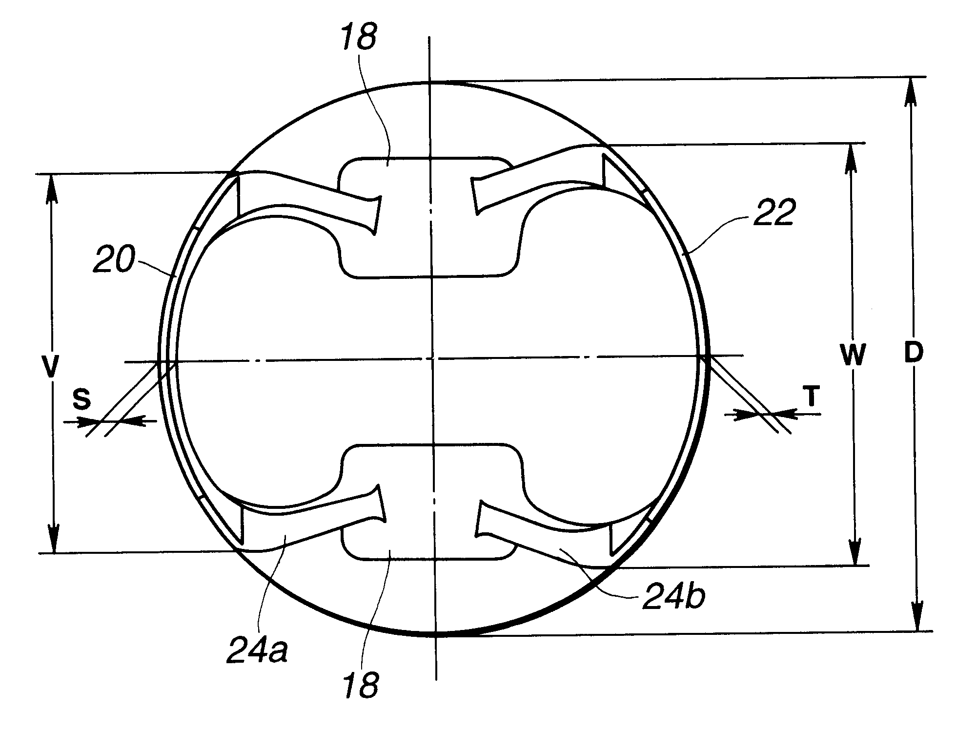
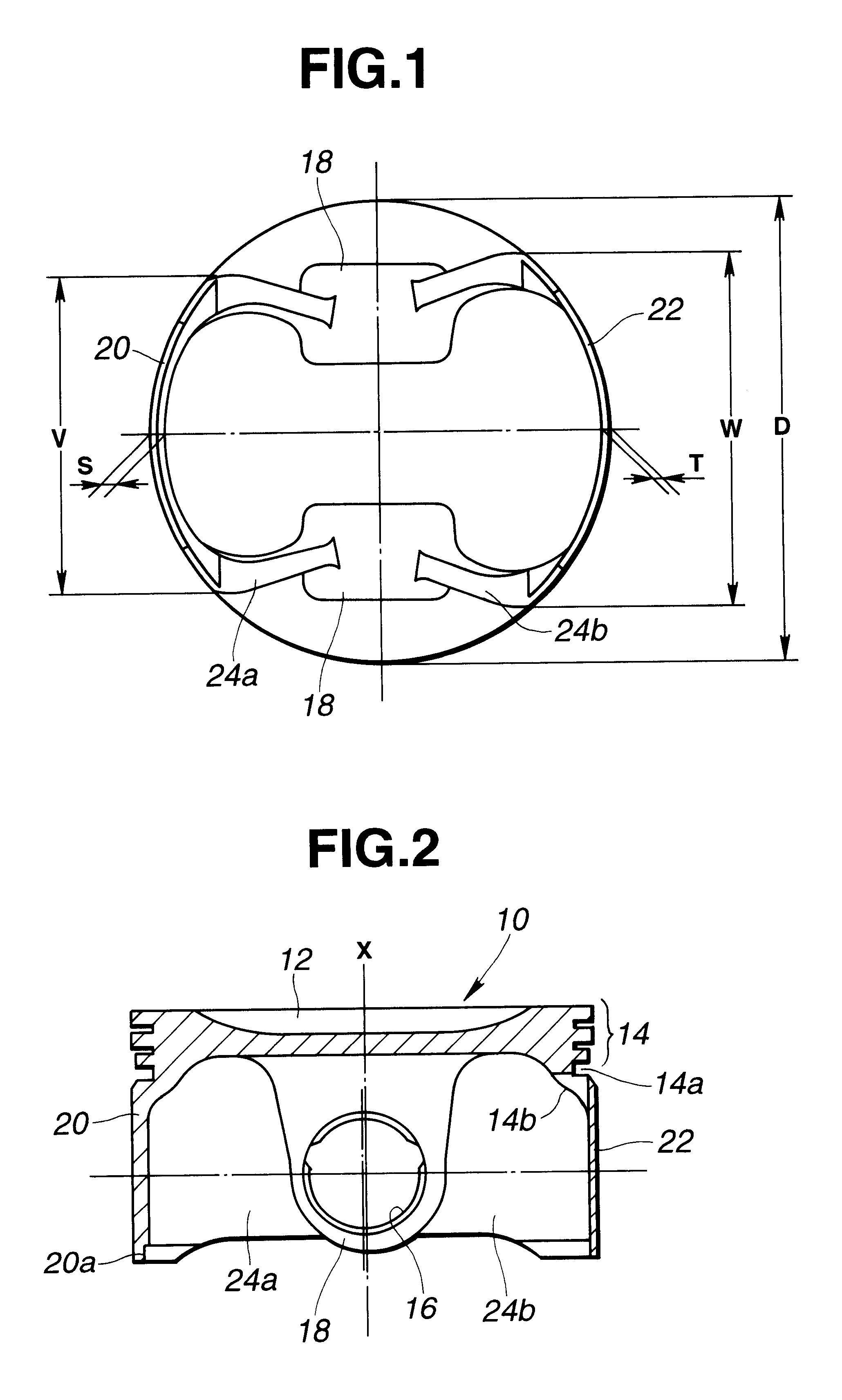
Referring now to the drawings, particularly to FIGS. 1 and 2, a piston 10 of the embodiment is formed into a substantially inverted cup-like shape. The piston 10 of the first embodiment comprises a piston crown portion or a piston head portion 14 constructing a top face of the piston, a pair of piston pin-boss portions (18, 18), a major-thrust-side skirt portion 20, a minor-thrust-side skirt portion 22, and web-like apron portions 24a and 24b. The piston pin-boss portions (18, 18) are located on the underside of the piston crown portion 14, and integrally formed with the piston crown portion so that the pin-boss portions (18, 18) are spaced apart from each other in the axial direction of a piston pin or a gudgeon pin (not shown). Each of the piston pin-boss portions (18, 18) has a piston-pin bore or piston-pin hole 16 to which the piston pin is loosely fitted. The major-thrust-side skirt portion 20 and the minor-thrust-side skirt portion 22 are formed integral with the piston crown ...


PUM


Abstract

In a reciprocating piston of an internal combustion engine comprising a piston skirt having a major-thrust-side skirt portion and a minor-thrust-side skirt portion, a projected circumferential width of the minor-thrust-side skirt portion is greater than a projected circumferential width of the major-thrust-side skirt portion. Additionally, the piston skirt is dimensioned so that the minimum thickness of the minor-thrust-side skirt portion is less than the minimum thickness of the major-thrust-side skirt portion.

Description

BACKGROUND OF THE INVENTION1. Field of the InventionThe present invention relates to the improvements of a reciprocating piston of an internal combustion engine suitable for automotive vehicles.2. Description of the Prior ArtIn reciprocating pistons used for automotive internal combustion engines, during reciprocating motion of the piston, the piston serves to transmit combustion pressure through a piston pin and a connecting rod to a crank pin and thus convert the combustion pressure into rotational force (torque) of an engine crankshaft. The piston operates with the piston crown or piston head exposed to extremely hot combustion gases, whereas the piston skirt contacts the comparatively cool cylinder wall. This results in a temperature gradient from the top of the piston to the bottom. Generally, the temperature of the piston top exposed to the combustion chamber is higher than that of the piston bottom. Thus, there is a difference of thermal expansion from the top to the bottom. ...

Claims


Application Information

Patent Timeline
Patent Type & Authority Patents(United States)
IPC IPC(8): F02F3/00F16J1/02
CPCF02F3/00F05C2251/042
Inventor WATANABE, HIROAKIMOTODA, SHINGO
Owner UNISIA JECS CORP
Why Eureka
Try Eureka