Device for reducing friction of guided region when forming high pressure in pipe

An internal high pressure forming and guiding area technology, applied in forming tools, metal processing equipment, manufacturing tools, etc., can solve the problems of reduced service life of molds, large friction in the guiding area, wear in the guiding area, etc., so as to improve the service life and reduce the tonnage. requirements, the effect of reducing the contact area

Inactive Publication Date: 2007-08-08
严格集团股份有限公司
View PDF1 Cites 44 Cited by
  • Summary
  • Abstract
  • Description
  • Claims
  • Application Information

AI Technical Summary

Problems solved by technology

[0004] The purpose of the present invention is to solve the problems that the guide area of ​​the existing guide and sealing method has large friction, which makes the pipe easy to thin and crack, the guide area wears seriously, and the overall service life of the mold is reduced. The device of guiding area friction, it comprises mold 8, left punch 7 and right punch 9, and described mold 8 is made up of upper mold 1 and lower mold 2 and upper mold 1 and lower mold 2 jointly combine molding cavity 10, mold 8 The left end of the left end is provided with the left guide hole 16 that communicates with cavity 10, and the right end is provided with the right guide hole 17 that communicates with cavity 10, and the axis of left punch 7, right punch 9 coincides with the axis of mold 8, and the axis of right punch The inside of the head 9 is provided with a liquid inlet hole 5, the left guide hole 16 and the right guide hole 17 of the mold 8 are counterbores, the right end center of the left punch 7 is provided with a right circular table body 11 and a right guide ring is provided at the root of the right circular table body 11 Groove 12, the left end center of right punch 9 is provided with left round table body 22 and left round table body 22 roots have left guide ring groove 4, and the right end of left punch 7 is installed in the left guide hole 16, and the outside of left punch 7 The cylindrical side wall is in clearance fit with the left guide hole 16, the left end of the right punch 9 is installed in the right guide hole 17, and the outer cylindrical side wall of the right punch 9 is in clearance fit with the right guide hole 17 of the mold 8

Method used


Image

  • Device for reducing friction of guided region when forming high pressure in pipe

Examples


specific Embodiment approach 1

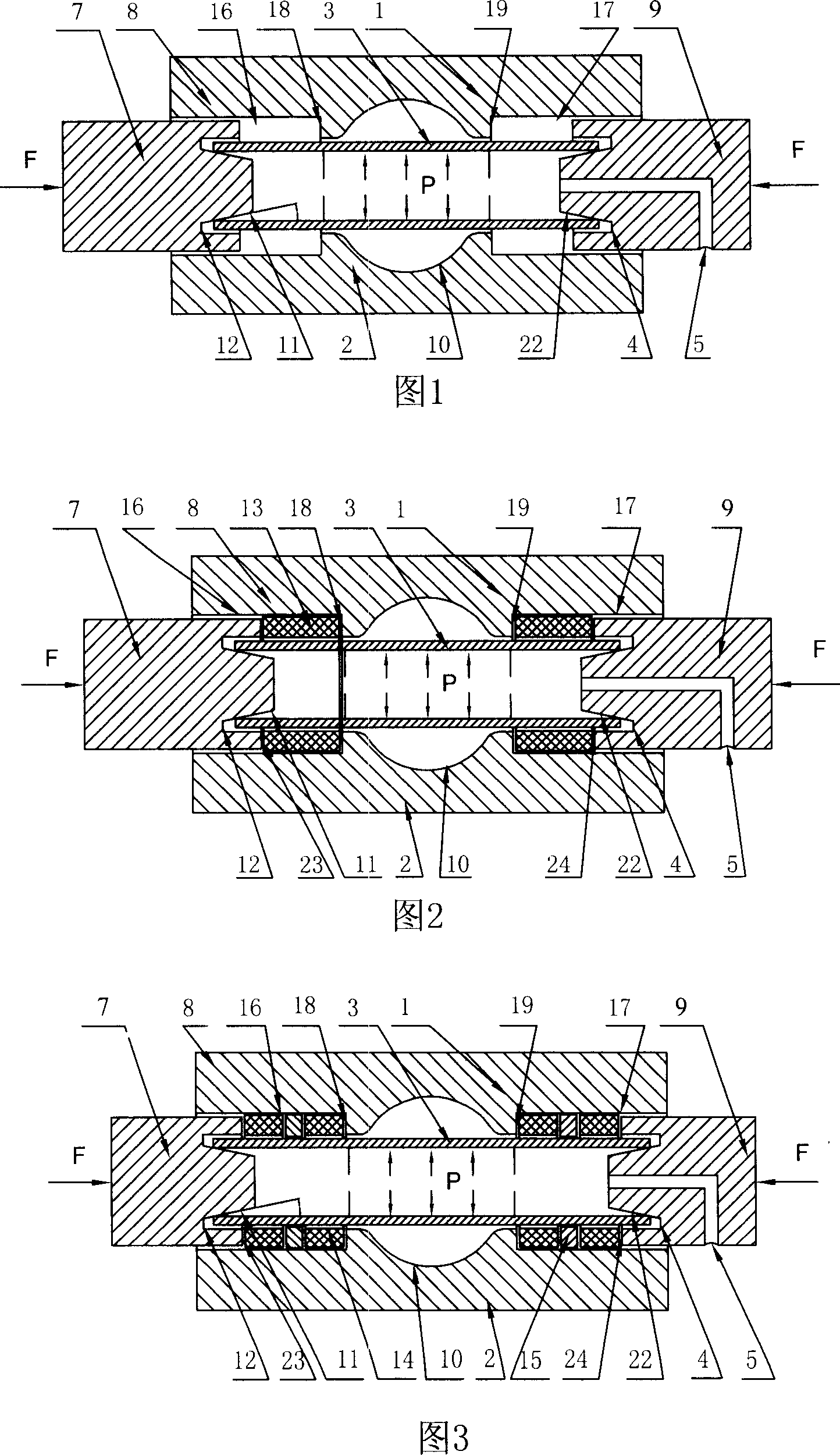
[0007] Specific embodiment one: (referring to Fig. 1), present embodiment is made up of mold 8, left punch 7 and right punch 9, and described mold 8 is made up of upper mold 1 and lower mold 2 and upper mold 1 and lower mold 2 The molding cavity 10 is combined together. The left end of the mold 8 is provided with a left guide hole 16 communicating with the cavity 10, and the right end is provided with a right guiding hole 17 communicating with the cavity 10. The mold 8 is installed on a vertical press in a conventional manner. The axes of the punch 7 and the right punch 9 coincide with the axis of the mold 8, and the inside of the right punch 9 is provided with a liquid inlet 5 through which high-pressure liquid enters, and the left guide hole 16 and the right guide hole 17 of the mold 8 are counterbores. The center of the right end of the left punch 7 is provided with a right round table body 11 and the root of the right round table body 11 has a right guide ring groove 12, an...

specific Embodiment approach 2

[0009] Specific embodiment two: (referring to Fig. 2) the difference between this embodiment and specific embodiment one is: this embodiment also comprises the first polyurethane ring 13, and the inner shoulder end surface 18 of the left guide hole 16 and the left punch 7 A first polyurethane ring 13 is respectively housed between the peripheral circular ring end face 23 of the right guide hole 17 and the peripheral circular ring face 24 of the right punch 9 between the inner shoulder end face 19 of the right guide hole 17. When the punches on both sides move inward, the pipe end will expand under the action of the punch circular platform and fit to the inner wall of the outer ring of the punch to achieve a reliable seal; control the axial thrust and displacement of the punch and the pipe 3 The internal liquid pressure deforms the pipe material 3 and finally fits the wall of the mold cavity 10 to obtain a formed part. After the processing is completed, the part is taken out, an...

specific Embodiment approach 3

[0010] Specific embodiment three: (referring to Fig. 3) the difference between this embodiment and specific embodiment one is: this embodiment also comprises second polyurethane ring 14 and metal ring 15, and the inner shoulder end surface 18 of left guide hole 16 is connected with Two second polyurethane rings 14 are respectively housed between the peripheral annular end faces 23 of the left punch 7 and between the inner shoulder end faces 19 of the right guide hole 17 and the peripheral annular end faces 24 of the right punch 9, and each A metal ring 15 is arranged between the two second polyurethane rings 14 respectively. When the punches on both sides move inward, the pipe end will expand under the action of the punch circular platform and fit to the inner wall of the peripheral ring of the punch to achieve reliable sealing; control the axial thrust, displacement and pipe material of the punch 3 The internal liquid pressure deforms the pipe 3 and finally fits the wall of t...


PUM


Abstract

The invention relates to a device for reducing guiding zone friction in high pressure formation of tubular material. It comprises dies, left punch head, right punch head, right round body on the right end face of the left punch head with right guiding ring slot, so does the right punch head, with gaps between the die, left punch head and the right punch head. It can eliminate the high touch pressure zone of the tubular end and the die guiding zone inner wall, reducing the friction resistance to improve production efficiency and die durability, and lowered requirement for tonnage.

Description

technical field [0001] The invention relates to hydroforming equipment for hollow parts, in particular to an internal high-pressure forming device for pipes. Background technique [0002] At present, in the fields of aircraft and automobiles, hollow parts can not only reduce weight, save materials, and reduce energy consumption during operation, but also ensure the strength and rigidity of structural parts. Therefore, hollow parts are widely used for components that are mainly subjected to bending and torsional loads. Tube high pressure forming is an advanced method for producing hollow variable cross-section lightweight structural parts. For example, the publication date is April 25, 2001, and the Chinese utility model patent whose notification number is CN2427399YA discloses such a kind of hydroforming equipment for hollow parts. The process is realized in this way: first put the pipe blank into the mold, and then use the vertical press to clamp the mold; the hydraulic p...

Claims


Application Information

Patent Timeline
Patent Type & Authority Applications(China)
IPC IPC(8): B21D26/02B21D37/12B21D26/033B21D26/047
Inventor 何祝斌苑世剑
Owner 严格集团股份有限公司
Why Eureka
Try Eureka