

Rotary compressor
A rotary compressor and motor assembly technology, applied to rotary piston/oscillating piston pump components, mechanical equipment, machines/engines, etc., can solve the difficulty of lubrication and sealing of the compressor's kinematic mechanism and reduce the performance of the compressor and reliability, low heat transfer efficiency of the air conditioning system, etc., to achieve good oil and gas separation effect, reduce noise, and simple and reasonable structure
- Summary
- Abstract
- Description
- Claims
- Application Information
AI Technical Summary
Problems solved by technology
Method used
Image

Examples
no. 1 example
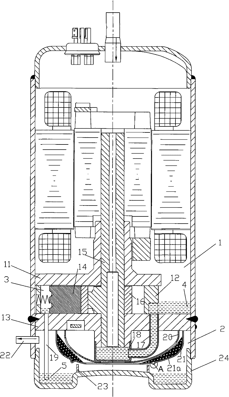
[0028] See 1- figure 2 , the rotary compressor includes a compression assembly and a motor assembly arranged in the casing, the compression assembly is located in the lower part of the casing, the motor assembly is located in the upper part of the casing, and the compression assembly includes a cylinder 12, a piston and a slider arranged in the cylinder 12 The piece 14, the long bearing 11 and the short bearing 13 for supporting the eccentric crankshaft 15 are arranged on the cylinder 12, and the inner space of the housing is divided into the upper low-pressure chamber 1 and the lower high-pressure chamber 2 by the short bearing 13, and the short bearing 13 is provided with upper oil sump 4.
[0029] In the low-pressure chamber 1 , the oil brought in by suction is separated and accumulated in the upper oil pool 4 of the short bearing 13 . The lower end of the short bearing 13, that is, the boss end of the short bearing 13, is sleeved with an oil guide cover 18, and the oil g...
no. 2 example
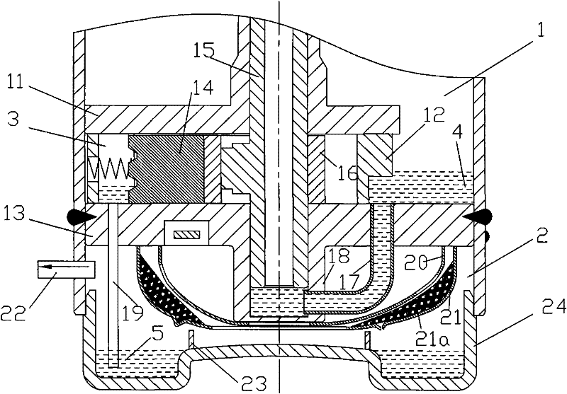
[0036] see image 3, In this embodiment, the oil guide cover 18 is eliminated, and a blind hole is provided at the lower end of the short bearing 13, and the blind hole and the eccentric bearing together form an oil storage chamber.
[0037] See the first embodiment for the rest of the undescribed parts, and will not repeat them here.
no. 3 example
[0039] see Figure 4 , In this embodiment, the lower oil pool 5 located in the lower casing 24 is set on the bottom side of the casing, and the groove is a single groove, rather than an annular groove as in the first embodiment.
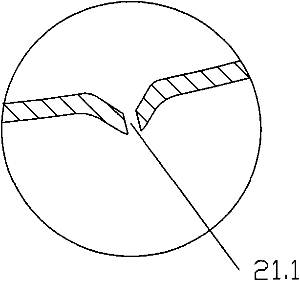
[0040] The side of the inner muffler 20 is provided with more than one internal outlet, which is formed by the inner muffler filter screen 20a; the side of the outer muffler 21 is provided with more than one outer outlet, and the outer outlet An outer muffler filter screen 21a is arranged on the outlet, and the setting directions of the inner muffler filter screen 20a and the outer muffler filter screen 21a are opposite; The outer discharge port on the outer muffler 21 is arranged on the direction 180 degrees apart from the groove on the lower oil pool 5 .
[0041] See the first embodiment for the rest of the undescribed parts, and will not repeat them here.
PUM
 Abstract
Description
Claims
Application Information