Substrate-storing container

a technology for storage containers and substrates, applied in the direction of tray containers, transportation and packaging, packaging goods types, etc., can solve the problems of affecting the quality of substrates, the mold for forming the container body b>1/b> becoming complex, and the door tightly sticking to the container body b>1/b> and becoming difficult to open

Active Publication Date: 2005-11-10
SHIN-ETSU POLYMER CO LTD
View PDF19 Cites 43 Cited by
  • Summary
  • Abstract
  • Description
  • Claims
  • Application Information

AI Technical Summary

Benefits of technology

[0026] Further, when low-frictional resistance portions having low frictional resistance are formed in the substrate contact area of the shelf element, no substrate will stop partway within the holding groove of the ret...

Problems solved by technology

Though the substrates of this type contributes to development of chips into large size and improvement of productivity, they are liable to flex due to gravity when placed either horizontally or when stood upright.
However, this requirement may cause differential air pressure between inside and outside due to high speed transportation such as air shipment etc., and such differential air pressure may cause a fear of the door tightly sticking to container body 1 and becoming difficult to open.
Because, in the case of a filter-equipped configuration, it is necessary to form a screw hole and screw a resinous inter pressure adjustment device into this screw hole, the problem of the mold for forming container body 1 becoming complex occurs.
Specifically, formation of the container body 1 with a mold inevitably necessitates a rotary mechanism when the mold is separated, so that it is impossible to make the mold structure simple.
Also in this case, because some slide structures for avoidance of undercuts for mold separation are needed, it is impossible to avoid the mold structure from being complicate...

Method used


Image

  • Substrate-storing container
  • Substrate-storing container
  • Substrate-storing container

Examples


example

[0075] A container body of a substrate storage container shown in FIG. 8 was injection molded using polycarbonate, so that low-frictional resistance portions 23 having an average surface roughness (Ra) of 0.3a (0.3 μm) were formed by a grain finish treatment. The surface roughness was measured by a probe contact type surface roughness tester [a Mitutoyo model, trade name: Surf test 501]. In this configuration, a 300 mm wafer (silicon wafer) as a substrate was placed on the shalf, and the frictional resistance generated when the wafer was moved in the horizontal direction was measured by a push-pull gauge having a full scale of 50 N [a product of AIKOH ENGINEERING CO., LTD., trade name: AWF-50]. The measurement result is shown in Table 1. This measurement was done at six points, the 1st stack, 5th stack, 10th stack, 15th stack, 20th stack and 25th stack, from bottom, and the average value was calculated.


PUM


Abstract

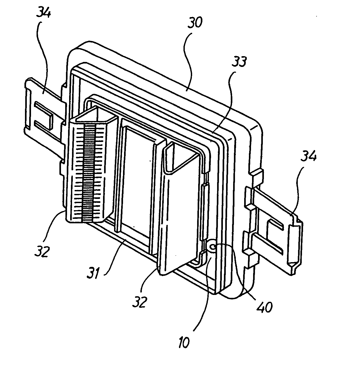
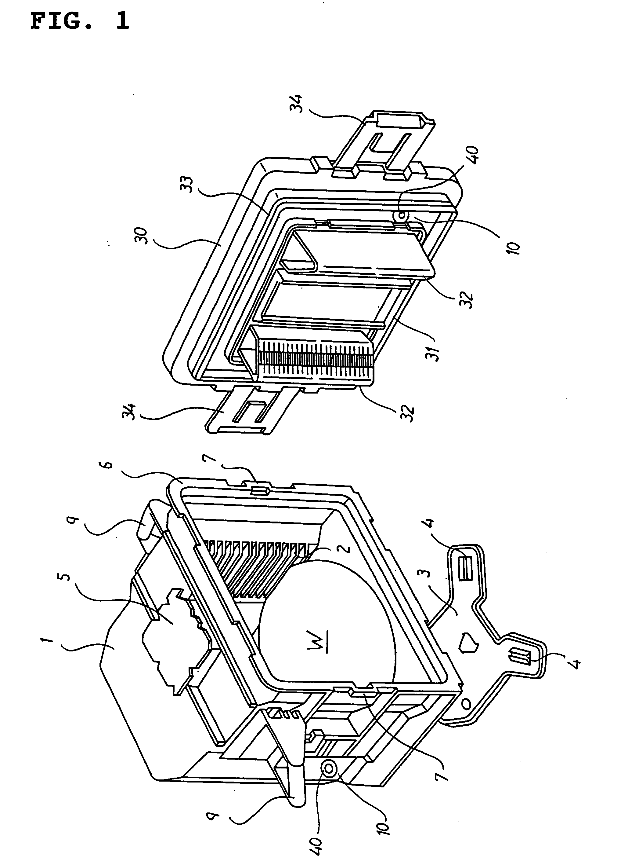
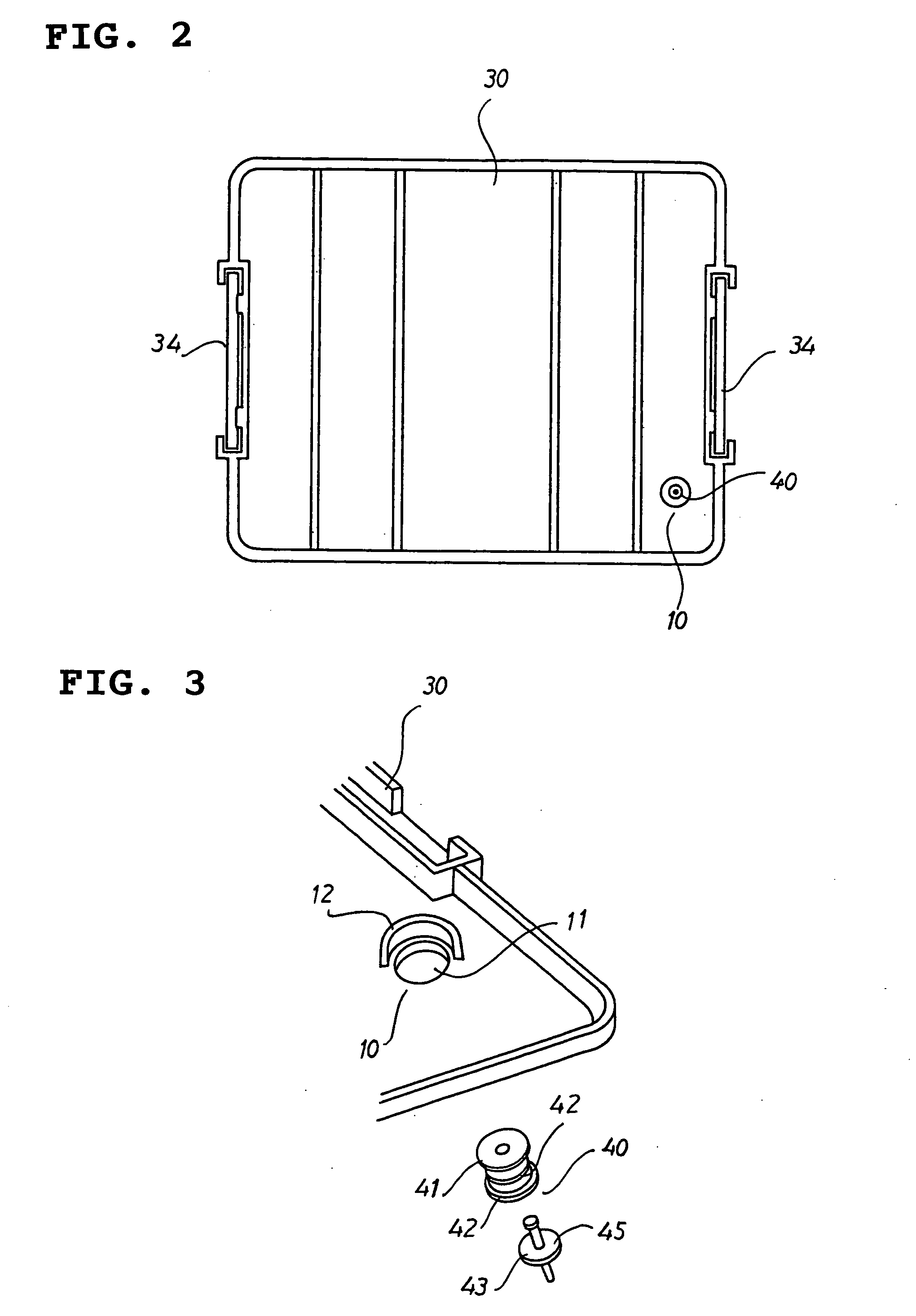
A substrate storage container which includes: a front-opening box type container body for storing a multiple number of substrates in alignment therein; a door for opening and closing the open front of the container body in a sealing manner; and inner-pressure adjustment devices attached to the mounting ports in the container body and the door for adjusting the pressure inside the container body closed with the door. The inner-pressure adjustment device is configured of an elastic attachment cylinder, a filter support structure fitted into, and protected by, the attachment cylinder and a multiple number of filters held inside the filter support structure. Since the inner-pressure adjustment device can be set by mounting an attachment cylinder of a simple structure by use of elastic deformation to the attachment hole, which is provided for the container body and/or the door, there is no need of forming screw holes which need time and effort.

Description

TECHNICAL FIELD [0001] The present invention relates to a substrate storage container for use in storage, transportation, keeping and processing and the like of semiconductor wafers, mask glasses or other substrates, and more detailedly relates to filters that control the differential air pressure between inside and outside the substrate storage container and a supporting structure for substrates. BACKGROUND ART [0002] In the recent semiconductor industry, in order to further enhance the productivity, substrates such as silicon wafers, glass wafers with a large-diametric size of 300 mm have started being used. Though the substrates of this type contributes to development of chips into large size and improvement of productivity, they are liable to flex due to gravity when placed either horizontally or when stood upright. Therefore, it is demanded that these substrates should be stored in a predetermined substrate storage container and handled safely so as to avoid damage to these. [0...

Claims


Application Information

Patent Timeline
IPC IPC(8): H01L21/673
CPCH01L21/67369H01L21/67393H01L21/67383H01L21/02H01L21/68
Inventor MIMURA, HIROSHINIIYA, WATARUYAJIMA, TOSHITSUGU
Owner SHIN-ETSU POLYMER CO LTD
Why Eureka
Try Eureka