
Component of an exhaust system and method of manufacturing such a component
a technology of exhaust system and component, which is applied in the direction of engine components, gas passages, silting apparatus, etc., can solve the problems of time-consuming assembly, and achieve the effect of simple manufacturing by winding
- Summary
- Abstract
- Description
- Claims
- Application Information
AI Technical Summary
Benefits of technology
Problems solved by technology
Method used
Image

Examples
first embodiment
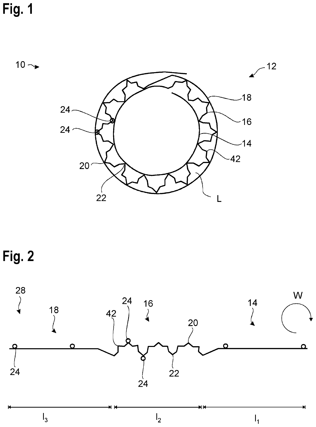
[0052]FIGS. 1 and 2 show a component 10 of an exhaust system according to a For reasons of clarity, where features occur several times, only some of them are provided with reference numerals in the figures.
[0053]The component 10 comprises a double-walled pipe 12, which may extend over any desired length and encloses a cavity in its interior. The component 10 may be made use of as an exhaust pipe, for example, but also in a muffler or as a housing for other suitable parts of an exhaust system which may be received in the interior of the double-walled pipe 12, if appropriate.
[0054]In this example, the double-walled pipe 12 includes three layers 14, 16, 18, of which the layer 14 constitutes the radially innermost layer and the layer 18 constitutes the radially outermost layer. The layer 16 is positioned between the layers 14 and 18 as viewed in the radial direction.
[0055]The layer 16 is a structured layer which has a wave structure with quite a number of wave crests 20 and wave trough...
second embodiment
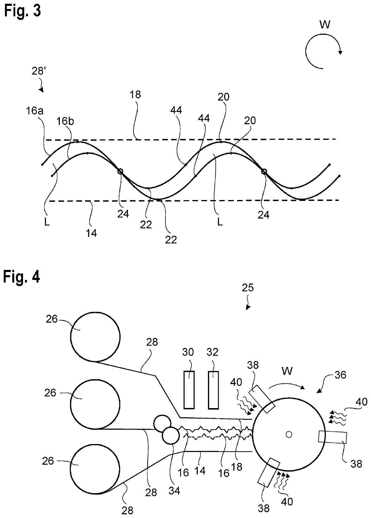
[0080]FIG. 3 illustrates a component according to the invention.
[0081]Here, the double-walled pipe 12 is produced by winding up a stack of two structured layers 16a, 16b, which are placed on top of each other as is illustrated in FIG. 4.
[0082]Each of the structured layers 16a, 16b here has a sinusoidal shape with the same period and the same amplitude. Of course, a different wave form could also be selected, which does not correspond to a mathematically exact sine, but also extends periodically and without any sharp bends, that is, discontinuities in the gradient.
[0083]The two structured layers 16a, 16b are shifted relative to each other such that they touch each other away from the wave crests 20 and the wave troughs 22, in this case by a phase of about π / 4. At these locations, the fixing points 24 are provided. The fixing points 24 are thus located in the region of a zero crossing 44 of the structured layer 16b or between the zero crossing 44 and the wave trough 22 of the structur...
PUM
 Abstract
Description
Claims
Application Information