Feeding device for feeding products onto a conveyor belt

a technology of conveyor belts and products, which is applied in the direction of conveyor parts, mechanical conveyors, transportation and packaging, etc., can solve the problems of undesirable displacement of products being fed, insufficient space available for segregation and separate supply, and devices known in practice that do not permit controlled feeding or arrangement of individual products, etc., to achieve simple and cost-effective effects

Active Publication Date: 2022-01-25
DICKFELD NILS
View PDF40 Cites 0 Cited by
  • Summary
  • Abstract
  • Description
  • Claims
  • Application Information

AI Technical Summary

Benefits of technology

The patent describes a system for positioning and arranging small products on a conveyor belt for quality control and further processing. It uses rolls with small indentations to create rows of products and can transfer rotating movement to the products between rolls, allowing for easy quality control and processing. The system can also easily adjust the distance between the rows of products, making it suitable for different product needs. Overall, the system is simple, affordable and efficient for automating quality control and processing.

Problems solved by technology

The feeding devices known in practice often do not permit a controlled feeding or arrangement of individual products on the conveyor belt.
In the case of a storage container that is arranged directly above the conveyor belt, the space available for the segregation and separate supply is often inadequate.
The transport speed of the feeding belt in this case corresponds as precisely as possible to the conveying speed of the conveyor belt, so that the products do not experience any acceleration in the conveyor direction of the conveyor belt during the transfer from the feeding belt to the conveyor belt, which could lead to an undesirable displacement of the products being fed.

Method used


Image

  • Feeding device for feeding products onto a conveyor belt
  • Feeding device for feeding products onto a conveyor belt
  • Feeding device for feeding products onto a conveyor belt

Examples


Embodiment Construction

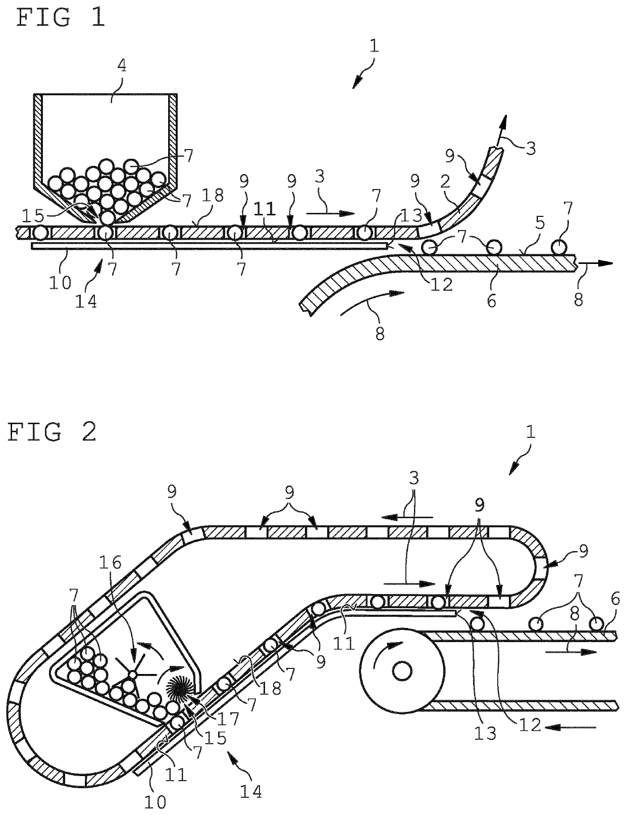
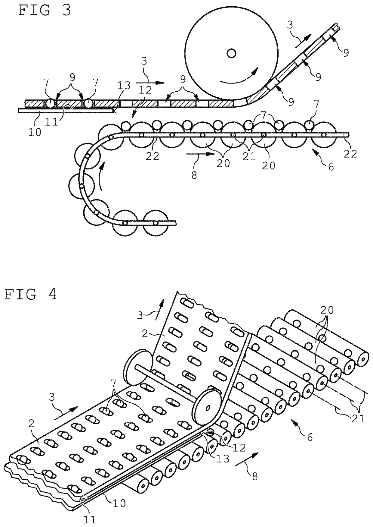
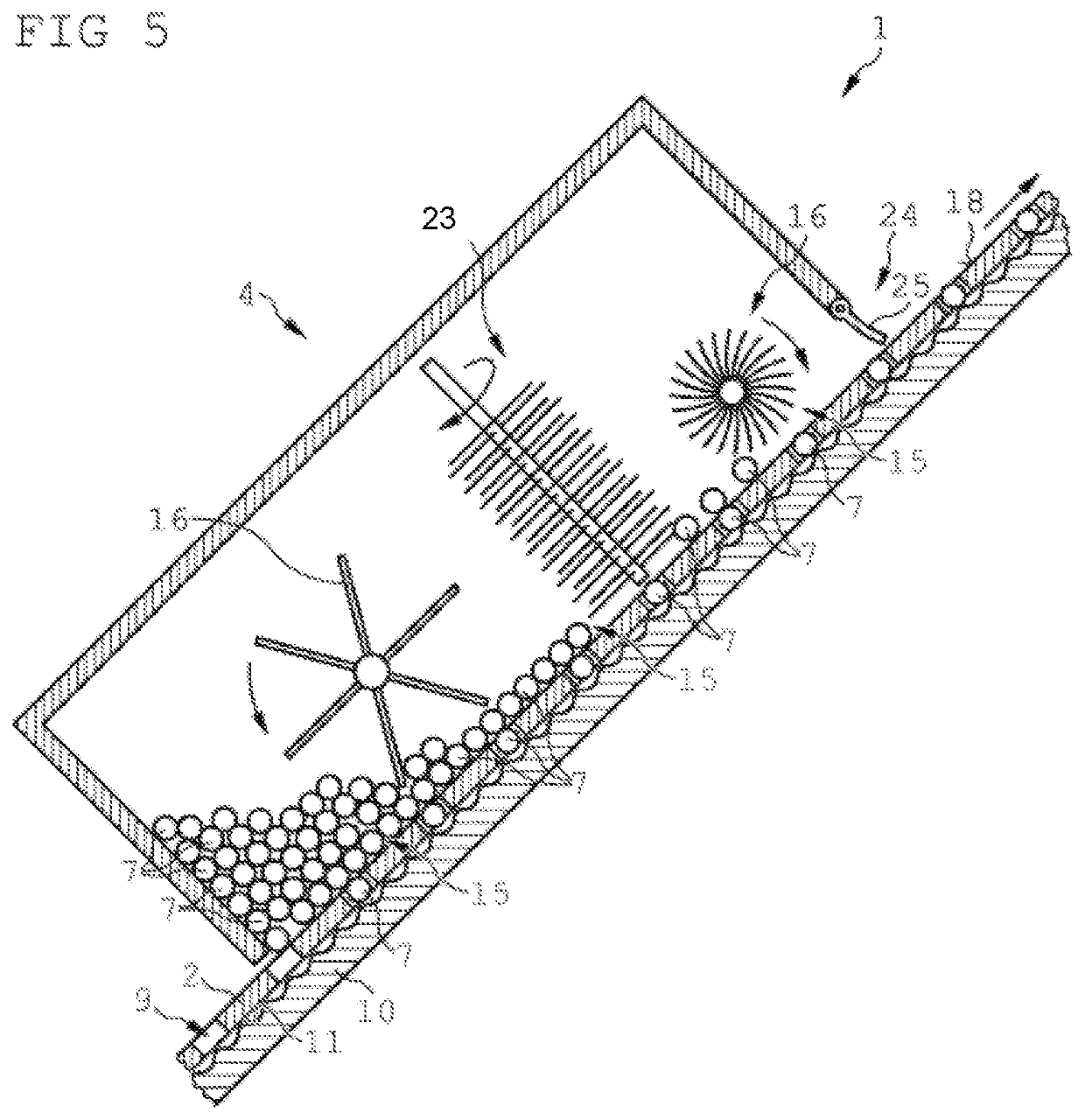
[0029]A feeding device 1 illustrated in FIGS. 1 to 4 in different variants has a feeding belt 2, which is guided by a forced guidance (not illustrated in detail in the figures) in a direction of transport indicated by an arrow 3 from a storage container 4 to an upper side 5 of a conveyor belt 6. In the storage container 4 there area number of products 7 that are to be fed on to the conveyor belt 6 in a controlled manner, in order to then be conveyed by the conveyor belt 6 in a conveyor direction indicated by an arrow 8 from the storage container 4 to a destination not shown in the figures. The products 7 shown in the exemplary embodiments are pharmaceutical capsules, but almost any other products that can be delivered from a storage container 4 could also be fed from the storage container 4 on to the conveyor belt 6.

[0030]In the feeding belt 2, multiple holes 9 are formed at a distance from one another in the direction of transport 3. The dimensions of each hole 9 are adapted to the...


PUM


Abstract

A feeding device for feeding products from a storage container on to a conveyor belt moving in a conveyor direction is provided wherein a feeding belt at a storage container opening on a lower side of the storage container receives products to be conveyed and transports them to an upper side of the conveyor belt, in order to deliver the products on to the conveyor belt in a feeding region on the upper side of the conveyor belt, the feeding belt has a number of holes, the dimensions of which are adapted to the products to be conveyed such that a respective product can fall through an associated hole. A guiding element extending from the storage container opening to the feeding region on the upper side of the conveyor belt, including a guiding surface arranged directly below the feeding belt, is arranged on a lower side of the feeding belt in such a way that the guiding surface prevents the products from falling through the holes of the feeding belt until the products are delivered on to the upper side of the conveyor belt in the feeding region. The holes are arranged in the feeding belt in a matrix shape. The guiding surface of the guiding element forms a low-friction and abrasion-resistant flat sliding surface.

Description

BACKGROUND AND SUMMARY[0001]The invention relates to a feeding device for feeding products out of a storage container on to a conveyor belt moving in a conveyor direction, wherein a feeding belt receives products to be conveyed at a storage container opening on a lower side of the storage container and transports them to an upper side of the conveyor belt in order to deliver the products on to the conveyor belt in a feeding region on the upper side of the conveyor belt.[0002]Many different conveyor belts are known in practice, with which products that are located thereon can be conveyed in a conveyor direction defined by the path of the conveyor belt. The products to be conveyed in this case are generally placed on an upper side of the conveyor belt and conveyed by the conveyor belt over a defined conveying distance until the products are removed from the conveyor belt at the end of the conveying distance or supplied to a further processing step or a forwarding of the products. As t...

Claims


Application Information

Patent Timeline
Patent Type & AuthorityPatents(United States)
IPC IPC(8): B65G47/28B65G19/02B65G15/58B65G19/18B65G37/00B65G47/14
CPCB65G19/02B65G15/58B65G19/185B65G37/005B65G47/1407B65G47/1478B65G2201/0214B65G2201/047B65G2812/02168
InventorDICKFELD, NILS
OwnerDICKFELD NILS