
Stator for an electrical machine and method for production of a stator

a technology for stators and electrical machines, applied in the direction of electrical apparatus, dynamo-electric machines, structural associations, etc., can solve the problems of limiting the area of stators of the above-described type intended to be used in vehicles, thick cable harnesses, and increasing the space requirements of electric machines

Inactive Publication Date: 2002-04-09
ZF FRIEDRICHSHAFEN AG
View PDF12 Cites 91 Cited by
  • Summary
  • Abstract
  • Description
  • Claims
  • Application Information

AI Technical Summary

Benefits of technology

The stator according to the present invention allows automatic production of the interconnection arrangement in a simple and cost-effective manner and allows automatic interconnection of the individual coils. At the same time, the area required for the interconnection arrangement, and thus for the entire stator, is considerably reduced compared to the prior art.
The method according to the present invention allows simple, cost-effective interconnection of the individual stator coils to the connection conductors which may be automated. The advantages, influences, effects and method of operation of the method according to the invention is described above in the discussion of the stator according to the present invention.

Problems solved by technology

For example, the separate interconnection of the individual coils to the corresponding connections for connection to the electrical machine results in thick cable harnesses which add to the space requirements of the electric machine.
For example, a stator of the above-described type intended to be used in a vehicle is limited to the amount of area available in the engine compartment.
This requirement necessitates the use of additional insulation material and thus leads to a further increase in the required physical space.
Finally, there is also a risk that faults can occur when the coil ends are being associated and correspondingly interconnected.
Owing to the large number of wires, it is difficult to determine when a coil has been incorrectly connected, and when this situation occurs, which of the coils has been incorrectly connected.
If a short circuit occurs in the interconnection arrangement, it is difficult and time consuming to locate the defect point.
Furthermore, the known interconnection arrangement is also highly costly, since the interconnection process must be carried out by hand.
Automation of the process for production of such interconnection arrangements is impossible, so that the known interconnection arrangements are not suitable for large-scale production.
The fixing of the interconnection arrangement is necessary since, otherwise, the coil ends could tear off or be damaged.

Method used


Image

  • Stator for an electrical machine and method for production of a stator
  • Stator for an electrical machine and method for production of a stator
  • Stator for an electrical machine and method for production of a stator

Examples


Embodiment Construction

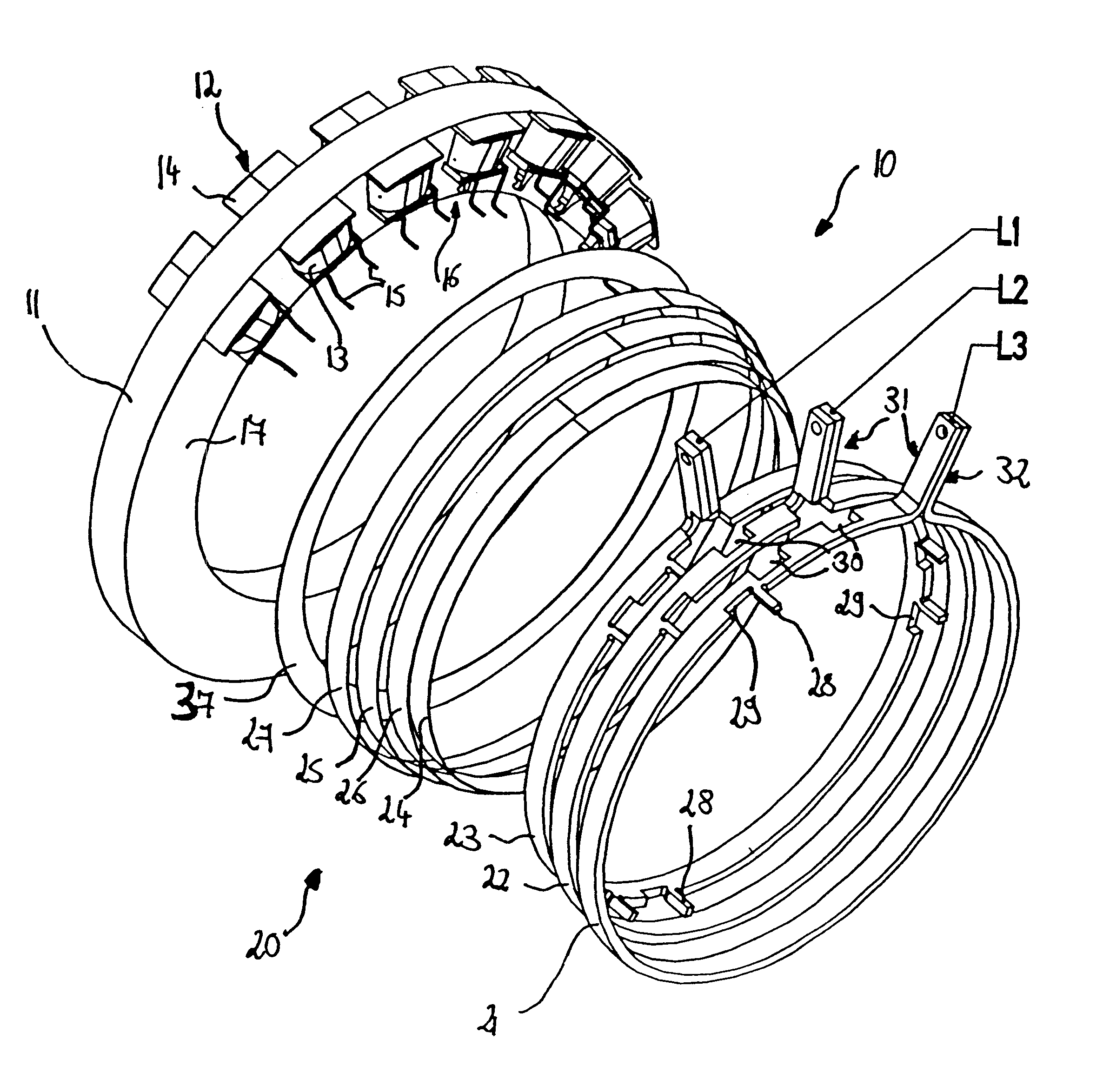
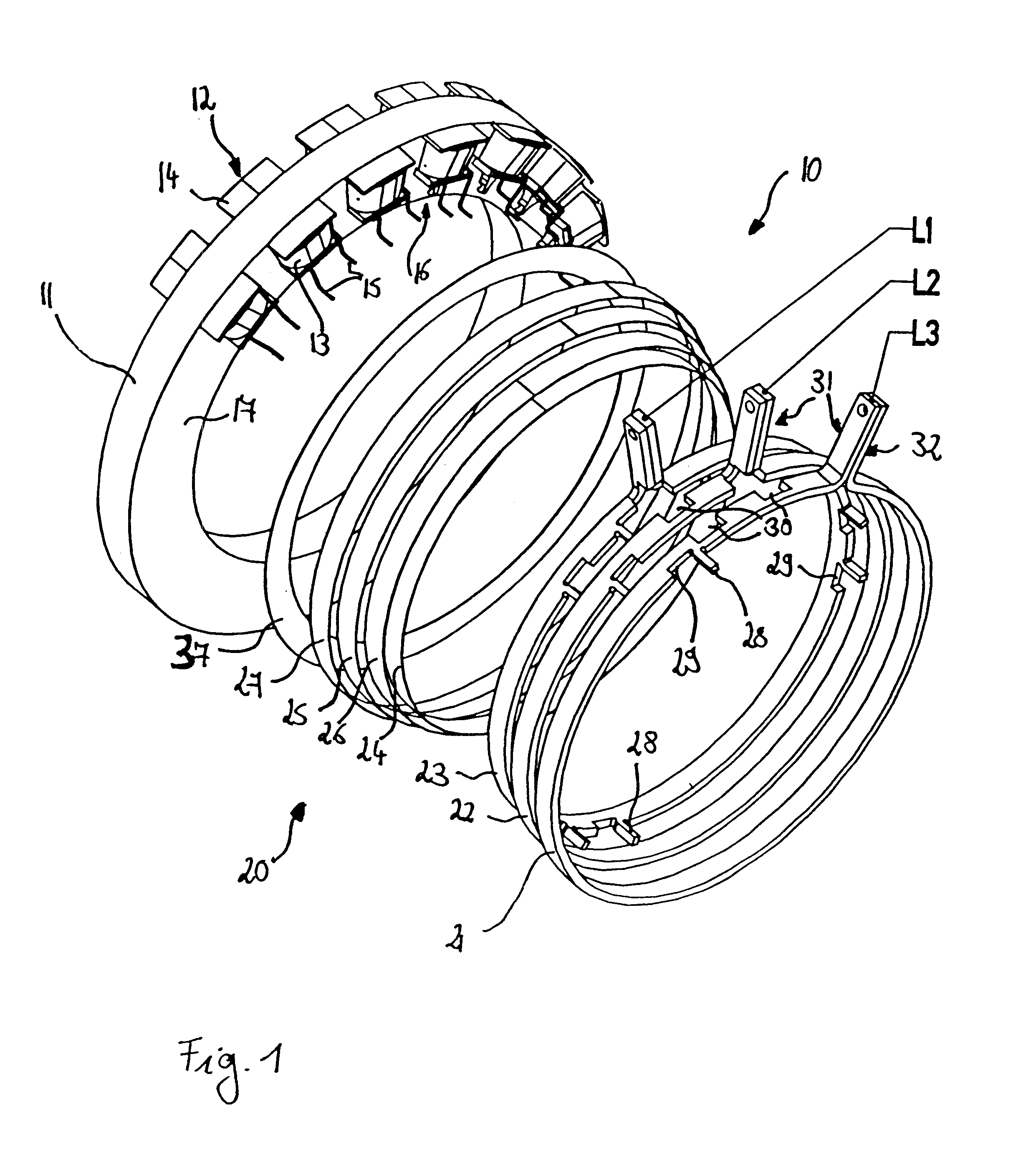
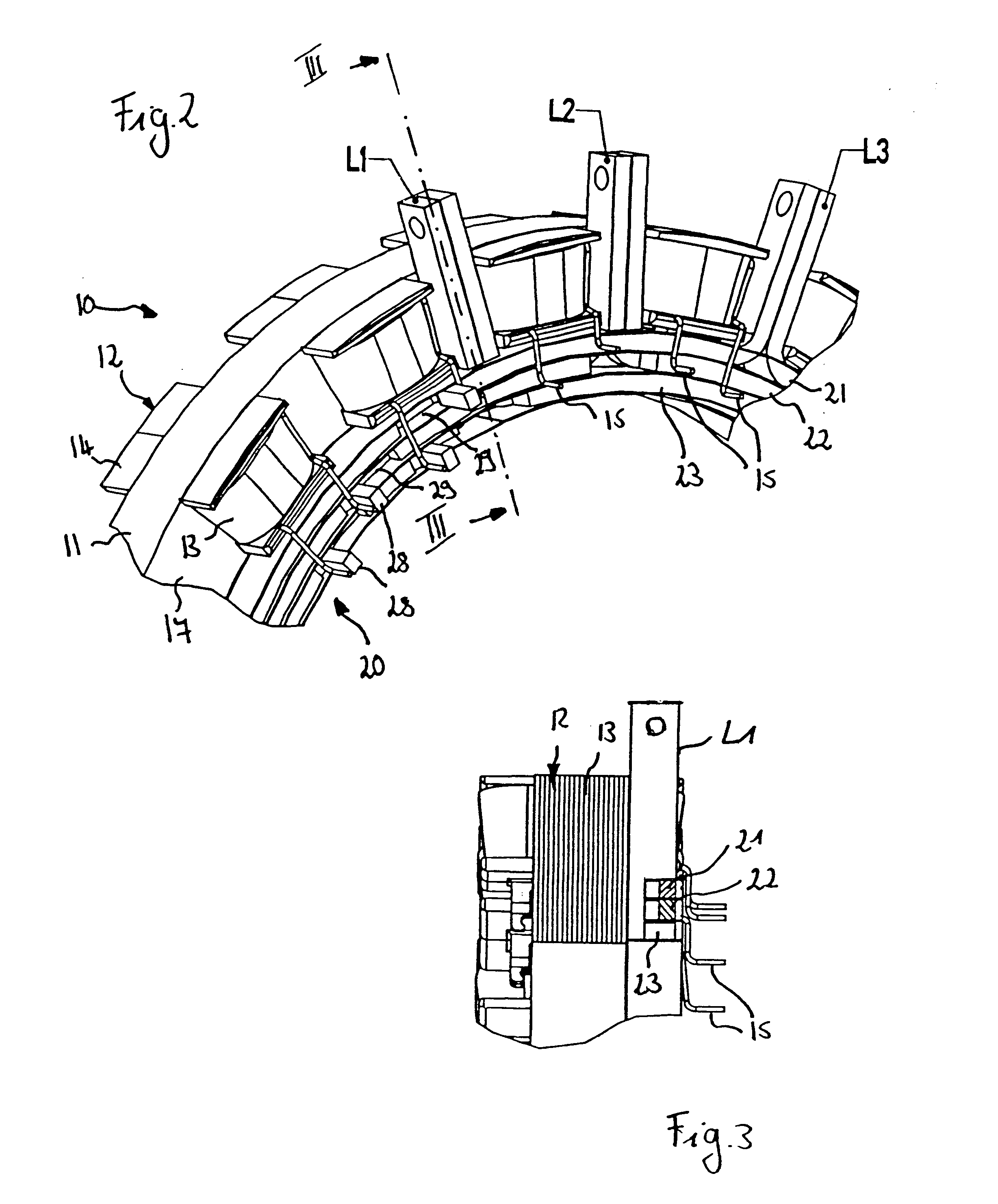
FIGS. 1 to 3 show a first embodiment of a stator 10 which is designed for use as a stator for an electrical machine. The present invention is particularly designed for use with a synchronous machine with permanent-magnet excitation such as a starter generator for a motor vehicle.

The stator 10 has a stator yoke 11 on which a plurality of stator coils 12 are arranged. The stator coils 12 each have an end winding 13 and an insulating body 14. The ends of the stator coil windings 13 are each formed by stator coil ends 15. The stator coils 12 are arranged around a circumference on the stator yoke 11 and thus form an area 16 bounded by the stator coils. This area 16 has a diameter formed by the distances between the stator coils 12 and the diameter of the stator yoke 11. The height of the area 16 results from the end windings 13 of the stator coils 12, that is to say from those regions of the end windings 13 which project beyond the stator yoke 11.

An interconnection arrangement 20 is prov...


PUM


Abstract

A stator for an electrical machine includes a stator yoke and a plurality of stator coils arranged on the stator yoke. An interconnection arrangement is arranged on one end face of the stator yoke. The interconnection arrangement has connecting conductors which are electrically insulated from one another. The connecting conductors are arranged concentrically with respect to one another and each have a different diameter. The connecting conductors have connections for the ends of the stator coils and for connection to the electrical machine. To minimize the space requirement of the stator and simultaneously allow the stator coils to be automatically interconnected in an automated manner, the interconnection arrangement is arranged inside an area bounded by the stator coils. Furthermore, the connections for the ends of the stator coils include connection projections designed such that they project outward at an angle to the respective connecting conductor to attach the stator coil ends. A number of cutouts are provided in the connection conductors and are arranged so that the connection projections are bendable into the cutouts once the coil ends have been connected.

Description

1. Field of the InventionThe present invention relates to a stator for an electrical machine including a plurality of stator coils arranged on a stator yoke and an interconnection arrangement arranged on one end face of the stator yoke having connecting conductors which are electrically insulated from one another and arranged concentrically with respect to one another. Each connecting conductor has a different diameter. The connecting conductors have connections for connection to the ends of the stator coils and for connection to the electrical machine. The present invention also relates to a method for producing such a stator.2. Description of the Related ArtStators for electrical machines generally have a plurality of stator teeth on which stator coils are wound. The coils are associated with individual phases of electrical power. The coils associated with a common phase are interconnected. In a three-phase machine the stator has three phases. Each of the phases have current appli...

Claims


Application Information

Patent Timeline
IPC IPC(8): H02K3/52H02K3/46H02K3/50H02K3/04H02K15/04
CPCH02K3/522H02K11/048H02K2203/12H02K2203/09H02K3/00
Inventor BAUMEISTER, JENSBAUCH-PANETZKY, DIETERKRAUSE, PETEROPPITZ, HORSTGRAU, EDMUNDSCHMITT, BERNHARDVAN HEYDEN, MARKUSSONNENBURG, REINHARDOCHS, MARTINTAREILUS, ALFREDWEIMER, JURGEN
Owner ZF FRIEDRICHSHAFEN AG
Learn More