

Constant voltage generator circuit provided with operational amplifier including feedback circuit
a constant voltage generator and feedback circuit technology, applied in the direction of electric variable regulation, process and machine control, instruments, etc., can solve problems such as malfunction of the i
- Summary
- Abstract
- Description
- Claims
- Application Information
AI Technical Summary
Benefits of technology
Problems solved by technology
Method used
Image



Examples
first embodiment
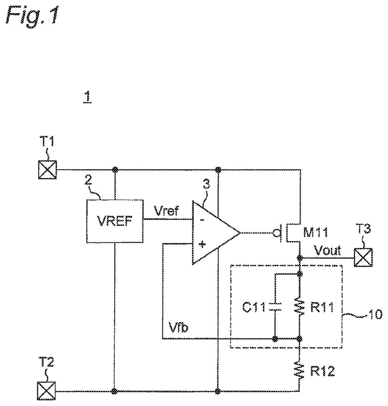
[0040]FIG. 5 is a circuit diagram showing a configuration example of a constant voltage generator circuit 1A according to a first embodiment. Referring to FIG. 5, the constant voltage generator circuit 1A is different from the constant voltage generator circuit 1 of FIG. 1 in such a point that a feedback circuit 10A is provided instead of the feedback circuit 10.
[0041]The present embodiment provides a constant voltage generator circuit that can prevent the DC offset from generating, in a constant voltage generator circuit including a differential amplifier circuit having a feedback circuit, when the high-frequency noise components outside the loop frequency band of the feedback system are inputted, by substantially matching each of the noise amplitudes propagating to the inverting input and the non-inverting input. In the present embodiment, in particular, in the feedback circuit 10A, each of the noise amplitudes propagating to the inverting input and the non-inverting input can be ...
second embodiment
[0074]FIG. 10 is a circuit diagram showing a configuration example of a constant voltage generator circuit 1B according to a second embodiment. Referring to FIG. 10, the constant voltage generator circuit 1B according to the second embodiment is characterized in that a feedback circuit 10B is provided in place of the feedback circuit 10A as compared with the constant voltage generator circuit 1A of FIGS. 5 and 6. The feedback circuit 10B is configured by connecting a resistor R13 in series with a series circuit of a resistor R11 and a capacitor C11.
[0075]When the condition of Equation (9) in the first embodiment is satisfied, a noise current flows through a parasitic capacitance C12. At this time, the configuration of the feedback circuit 10B according to the second embodiment has been devised as a method of superimposing a substrate noise Vn on the voltage potential of a feedback voltage Vfb.
[0076]FIG. 11 is a small signal equivalent circuit diagram showing noise paths P1 and P2 in...
examples
[0085]FIG. 13 shows an experimental result of a radio wave irradiation test for the constant voltage generator circuits of an example and a conventional example, and is a graph showing the frequency characteristics of an output voltage Vout. In this case, the conventional example is a constant voltage generator circuit related to a product manufactured by the applicant, and the example is an R1525 type constant voltage generator circuit manufactured by the applicant.
[0086]FIG. 13 shows fluctuations of the constant voltage generator circuit when the frequency of the radio wave is changed from 1 MHz to 1 GHz in the radio wave irradiation test. As is apparent from FIG. 13, in the conventional constant voltage generator circuit, the output voltage drops due to the influence of the DC offset caused by the superposition of harmonic noise components in the band of 100 kHz or more, which is the operating band of the constant voltage generator circuit. On the other hand, it can be seen that ...
PUM
 Abstract
Description
Claims
Application Information