Tip part for a vision device

a technology of vision device and tip, which is applied in the field of vision devices, can solve the problems of increasing and achieve the effect of improving the amount of stray light trapped in the optical well

Active Publication Date: 2022-07-12
AMBU AS
View PDF63 Cites 3 Cited by
  • Summary
  • Abstract
  • Description
  • Claims
  • Application Information

AI Technical Summary

Benefits of technology

[0012]A tip part for an endoscope and an endoscope including the tip part are provided. A first aspect of the disclosure relates to a tip part for an endoscope. In some embodiments, the tip part comprises a vision receptor able to provide an image from light received from an object to be investigated; a first light source; an exterior housing accommodating the vision receptor and the first light source; a proximal or back end for connection to other parts of the vision device, such as an insertion tube of an endoscope; and a distal or front end for receiving light received from the object; the exterior housing comprising a window positioned at the distal end, the window being of a transparent material so that light received from the object can pass through the window to the vision receptor, and so that light emitted from the first light source can pass through the window to the exterior, the window comprising an exterior surface positioned at least partly in front of the vision receptor and the first light source, wherein the window integrally comprises a first optical well of the transparent material, the optical well being an interior protrusion positioned between the first light source and the vision receptor so that a portion of light emitted from the first light source and reflected from the exterior surface enters the first optical well, whereby stray light is at least partially prevented from entering the vision receptor.
[0013]This may provide the advantage that the manufacture of the tip part may be simplified by having a window which covers the light source and the vision receptor. Furthermore, the optical well, or trap, may improve the image quality of the vision receptor by trapping stray light being internally reflected in the window, which would otherwise propagate to the vision receptor. Furthermore, assembly of the tip part may be improved by providing the window with an integral optical well. The integral optical well may further increase the amount of stray light being trapped in the optical well.

Problems solved by technology

The integral optical well may further increase the amount of stray light being trapped in the optical well.

Method used


Image

  • Tip part for a vision device
  • Tip part for a vision device
  • Tip part for a vision device

Examples


Embodiment Construction

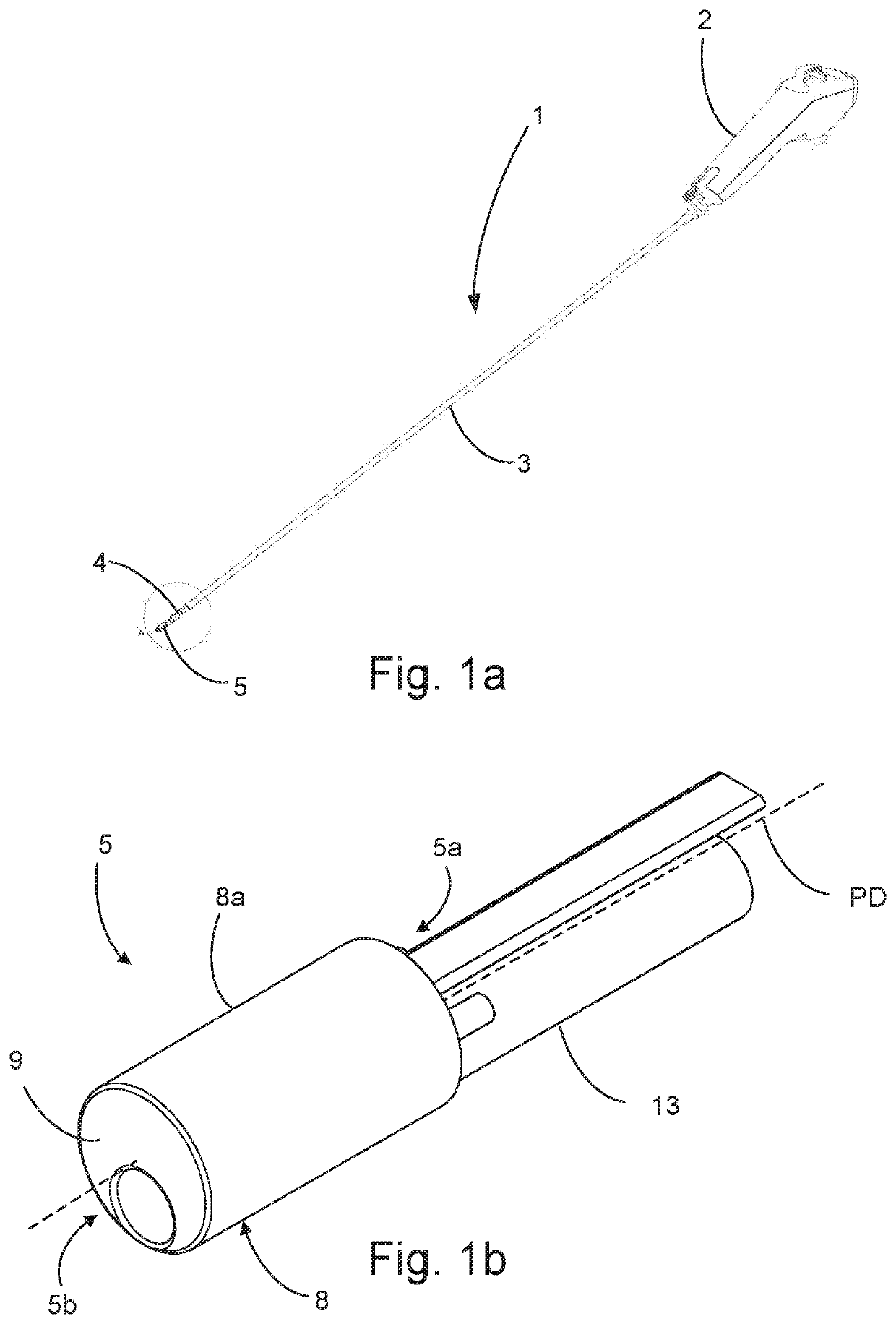
[0085]Turning first to FIG. 1a, an endoscope 1 exemplifying the vision device according to the disclosure is shown. The endoscope 1 comprises a handle 2 at the proximal end of the endoscope 1, an insertion tube 3 extending towards the distal end of the endoscope 1 where it comprises an articulated bending section 4, which, as the most distal segment, has a distal tip part 5 according to the disclosure. Though omitted for illustration purposes, the articulated bending section 4 will normally be covered by a suitable sleeve connected at least at its own distal end to the distal tip part 5, e.g. by means of an adhesive. The tip part 5 of the present disclosure is intended as a tip part 5 for a disposable endoscope 1 to be thrown away after use and therefore low manufacturing costs are an important issue.

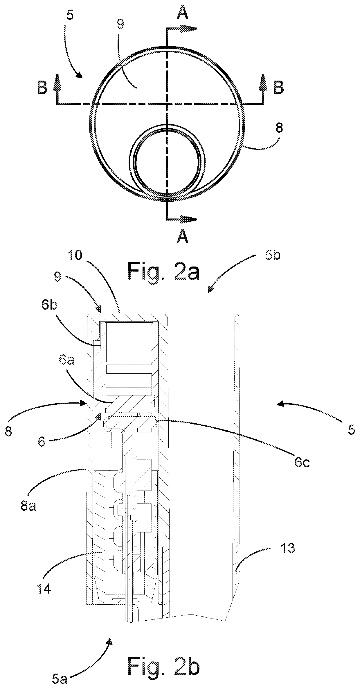
[0086]FIG. 1b shows a detailed embodiment of a tip part 5 for the endoscope shown in FIG. 1a. The tip part 5 has a proximal end 5a for connection to the insertion tube 3 of endoscope 1 ...


PUM


Abstract

A tip part for an endoscope has a vision receptor; a first light source; an exterior housing accommodating the vision receptor and the first light source; the exterior housing comprising a window positioned at a distal end of the tip part, the window being of a transparent material, the window comprising an exterior front surface positioned at least partly in front of the vision receptor and the first light source, wherein the window integrally comprises a first optical well of the transparent material, the first optical well being an interior protrusion positioned between the first light source and the vision receptor so that a portion of light emitted from the first light source and reflected from the exterior surface enters the first optical well, whereby stray light is at least partially prevented from entering the vision receptor.

Description

CROSS-REFERENCE TO RELATED APPLICATIONS[0001]This application claims priority from European Patent Application No. 18190733, filed on Aug. 24, 2018, which application is incorporated herein by reference thereto.FIELD OF THE DISCLOSURE[0002]The present disclosure relates to vision devices such as, but not limited to, endotracheal tubes and endoscopes, more specifically to a tip part of such a vision device and a vision device such as an endoscope with such a tip part.BACKGROUND[0003]Vision devices such as endoscopes are well known for visually inspecting inaccessible places such as human body cavities. Typically, the endoscope comprises an elongated insertion tube with a handle at the proximal end, as seen from the operator, and visual inspection means, such as a built-in camera, at the distal end of the elongated insertion tube. This definition of the terms distal and proximal, i.e. proximal being the end closest to the operator and distal being the end remote from the operator, as ...

Claims


Application Information

Patent Timeline
Patent Type & Authority Patents(United States)
IPC IPC(8): A61B1/00A61B1/07A61B1/05
CPCA61B1/00096A61B1/051A61B1/07A61B1/04A61B1/0676A61B1/0684A61B1/0008A61B1/00163A61B1/00165A61B1/00101A61B1/05
Inventor SØRENSEN, MORTEN
Owner AMBU AS
Why Eureka
Try Eureka