Optical lens

a technology of optical lenses and lenses, applied in the field of optical lenses, can solve the problems of discomfort to the human eye, negative influence, achieve the effect of avoiding discomfort and blurred vision, uniform illumination, and avoiding blurred vision

Inactive Publication Date: 2012-12-11
EDISON-OPTO
View PDF6 Cites 2 Cited by
  • Summary
  • Abstract
  • Description
  • Claims
  • Application Information

AI Technical Summary

Benefits of technology

[0007]The object of the present invention is to provide an optical lens, capable of redirecting the direction of illumination without using an inclined mechanism to achieve uniform illumination. In another aspect, light can be prevented from directly irradiating into the human eye, and the discomfort and blurred vision can be avoided.

Problems solved by technology

However, in practical use, since the dimensions of a single LED chip are extremely small, the light intensity can be quite high within an adjacent small area around the LED chip.
That may cause discomfort to the human eye when directly viewing the LED chip.
However, such a configuration may lead to a negative influence.
The upwardly inclined lamp holder may increase the possibility that the light source in the lamp holder may be directly viewed by the human eye thus cause discomfort and blurred vision.
And the above-mentioned situation will be worse when the LEDs are used as light sources in the street lamps, since the light intensity around the LED chip is higher than other conventional light sources.

Method used


Image

  • Optical lens
  • Optical lens
  • Optical lens

Examples


Embodiment Construction

[0021]The present invention is described below in detailed with the reference to accompanying drawings.

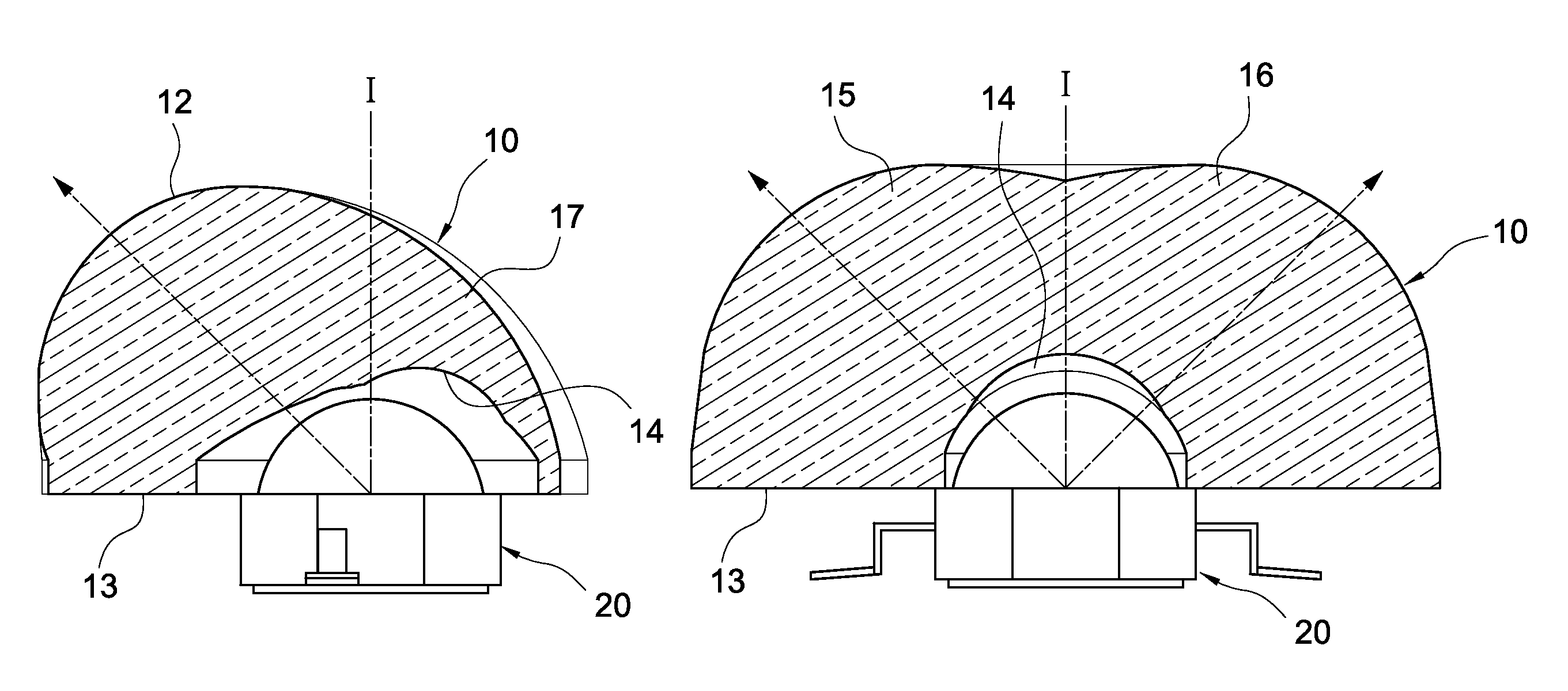
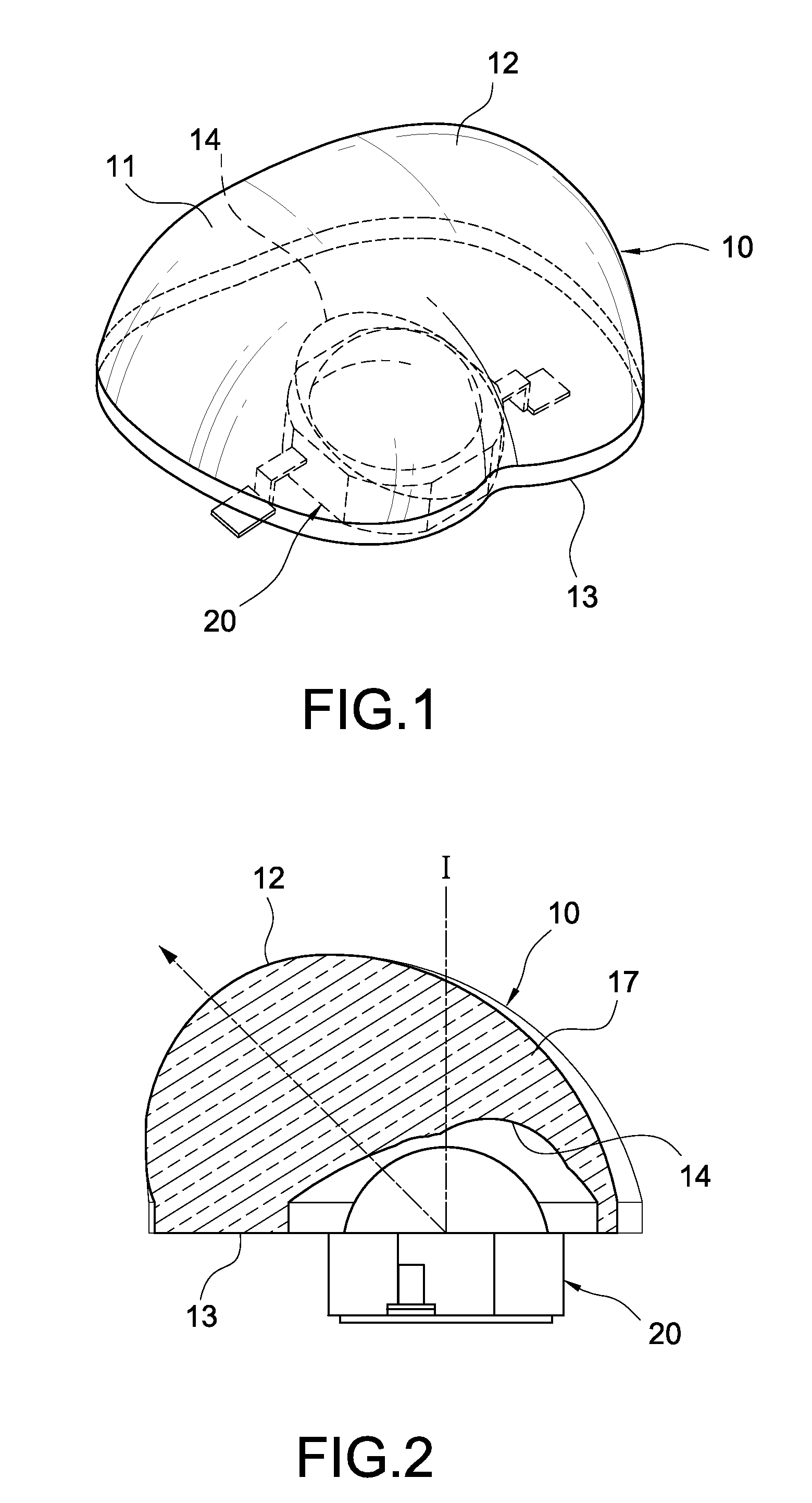
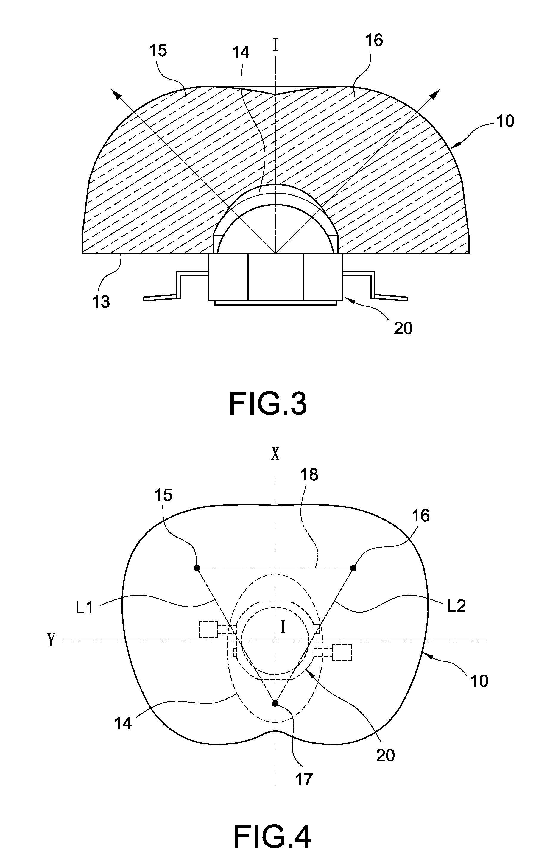
[0022]FIG. 1 shows a schematic view of the optical lens 10 according to an embodiment of the present invention. The optical lens 10 is arranged on a light emitting diode (LED) 20 for adjusting the illumination intensity distribution of the LED 20. The LED 20 is a surface mount device (SMD) type LED, but not limited thereto in practical use. The optical lens 10 includes a transparent main body 11, which may be made of glass, plastic or other transparent material. The main body 11 has an outer convex surface 12 and a bottom surface 13 opposite to the outer convex surface 12. The bottom surface 13 is designed to be a flat plane, such that the bottom surface 13 can increase the amount of total reflection. Therefore, the bottom surface 13 can decrease the amount of light extracting therefrom and increase the amount of the upwardly reflected light and then can increase the light extracti...


PUM


Abstract

An optical lens includes a main body having an outer convex surface and a bottom surface opposite to the outer convex surface. The bottom surface has an inner concave surface which is concave toward the outer convex surface. The outer convex surface and the inner concave surface cooperatively form two positive lens portions and a negative lens portion. The positive lens portions and the negative lens portion are arranged in a triangular configuration.

Description

BACKGROUND OF THE INVENTION[0001]1. Field of the Invention[0002]The present invention relates to an optical lens. More particularly, the present invention relates to an optical lens capable of forming a desired distribution of illumination intensity.[0003]2. Description of Related Art[0004]Having the advantage of saving energy, light emitting diodes (LEDs) are gradually replacing the traditional lamp bulbs and used as the next generation light sources for general lighting applications, which include indoor and outdoor lightings. However, in practical use, since the dimensions of a single LED chip are extremely small, the light intensity can be quite high within an adjacent small area around the LED chip. That may cause discomfort to the human eye when directly viewing the LED chip.[0005]Therefore, in practical applications, at least one optical element is often provided onto the LED chip for improving the uniform illumination and solving the above-mentioned problem of ultra-high lig...

Claims


Application Information

Patent Timeline
Patent Type & Authority Patents(United States)
IPC IPC(8): G02B3/10G02B13/18
CPCF21V5/04G02B3/02F21S8/086F21V5/007F21V5/08F21W2131/103F21Y2101/02F21Y2105/001F21Y2105/10F21Y2115/10
Inventor LU, MU-YINCHOU, HUNG-HSUN
Owner EDISON-OPTO
Why Eureka
Try Eureka