Stick-shaped cosmetic material dispensing container

a cosmetic material and stick-shaped technology, applied in the field of stick-shaped cosmetic material dispensing containers, can solve the problems of difficult for users to see a surface (e.g. skin, etc.), inconvenient for users, etc., to reduce shaken stick-shaped cosmetic material, prevent the effect of stick-shaped cosmetic material from breaking and minimize any visual obstruction

Active Publication Date: 2018-10-25
TOKIWA CORP
View PDF2 Cites 2 Cited by
  • Summary
  • Abstract
  • Description
  • Claims
  • Application Information

AI Technical Summary

Benefits of technology

[0009]According to one or more embodiments of the stick-shaped cosmetic material dispensing container, the container front portion includes the holding portion that holds the stick-shaped cosmetic material, and one of the concave portion and the convex portion extending in the axial direction extends to the holding portion. Further, the other (i.e. the contact portion of the cosmetic stick) of the concave portion or the convex portion extending in the axial direction and being held by the one (the concave portion or the convex portion of the holding portion) is formed on the outer peripheral surface of the stick-shaped cosmetic material. Accordingly, since one of the concave portion and the convex portion of the holding portion holds the other of the concave portion or the convex portion of the stick-shaped cosmetic material, the stick-shaped cosmetic material can be rigidly held by the holding portion by the convex portion being held by the concave portion. Therefore, shaking of the stick-shaped cosmetic material can be reduced and thus breakage of the stick-shaped cosmetic material can be prevented because the stick-shaped cosmetic material can be more rigidly held by the concave portion holding the convex portion even when a force is applied to the stick-shaped cosmetic material from almost any direction. Further, the shape of the stick-shaped cosmetic material when viewed from the front side is formed so as to be tapered as being separated from the opposing portion to the holding portion, that is to say, when viewed from the tip end (i.e. the front side), the stick-shaped cosmetic material is tapered from the contact portion toward the application portion. The width of the contact portion of the stick-shaped cosmetic material when viewed from the front side is substantially the same as the width of the holding portion when viewed from the front side. By setting the width of the holding portion to be substantially the same as the width of the stick-shaped cosmetic material, it is possible to minimize any visual obstruction when applying the cosmetic material (i.e. applying the make-up). Accordingly, since the holding portion minimizes the visual obstruction of the field of vision, the user can more easily view where to apply the make-up. Therefore, the usability can be improved.
[0010]Further, the concave portion which extends in the axial direction is formed on the inner peripheral surface of the container front portion, the convex portion which extends in the axial direction and is held by the concave portion is fowled on the outer peripheral surface of the stick-shaped cosmetic material, and a width of a portion of the convex portion entering the concave portion when viewed from the front side may be greater than a width of an opening portion of the concave portion when viewed from the front side. Here, when a force is applied to the stick-shaped cosmetic material in a direction such that the stick-shaped cosmetic material tends to be detached from the concave portion, the outside surface of the convex portion is pressed against the inside surface of the concave portion, and thus detachment of the convex portion from the concave portion and breakage can be reliably reduced. In other words, since the resistance of the stick-shaped cosmetic material to the force applied in a direction that tends to cause the convex portion to detach from the concave portion can be improved, the breakage of the stick-shaped cosmetic material can be more reliably reduced.
[0011]According to one or more embodiments, it is possible to prevent breakage of the stick-shaped cosmetic material and improve the usability.

Problems solved by technology

However, when a force is applied to the stick-shaped cosmetic material in a direction other than the front end portion side, there is a risk that the stick-shaped cosmetic material is shaken and / or broken.
Since the front end portion becomes a visual obstacle, it may be difficult for the user to see a surface (e.g. skin, etc.) where it is desired to apply the make-up and / or to see the make-up as it is being applied onto the surface.
Accordingly, the stick-shaped cosmetic material dispensing container of the related art may be inconvenient for a user to use, and there is a need to improve usability.

Method used


Image

  • Stick-shaped cosmetic material dispensing container
  • Stick-shaped cosmetic material dispensing container
  • Stick-shaped cosmetic material dispensing container

Examples


first embodiment

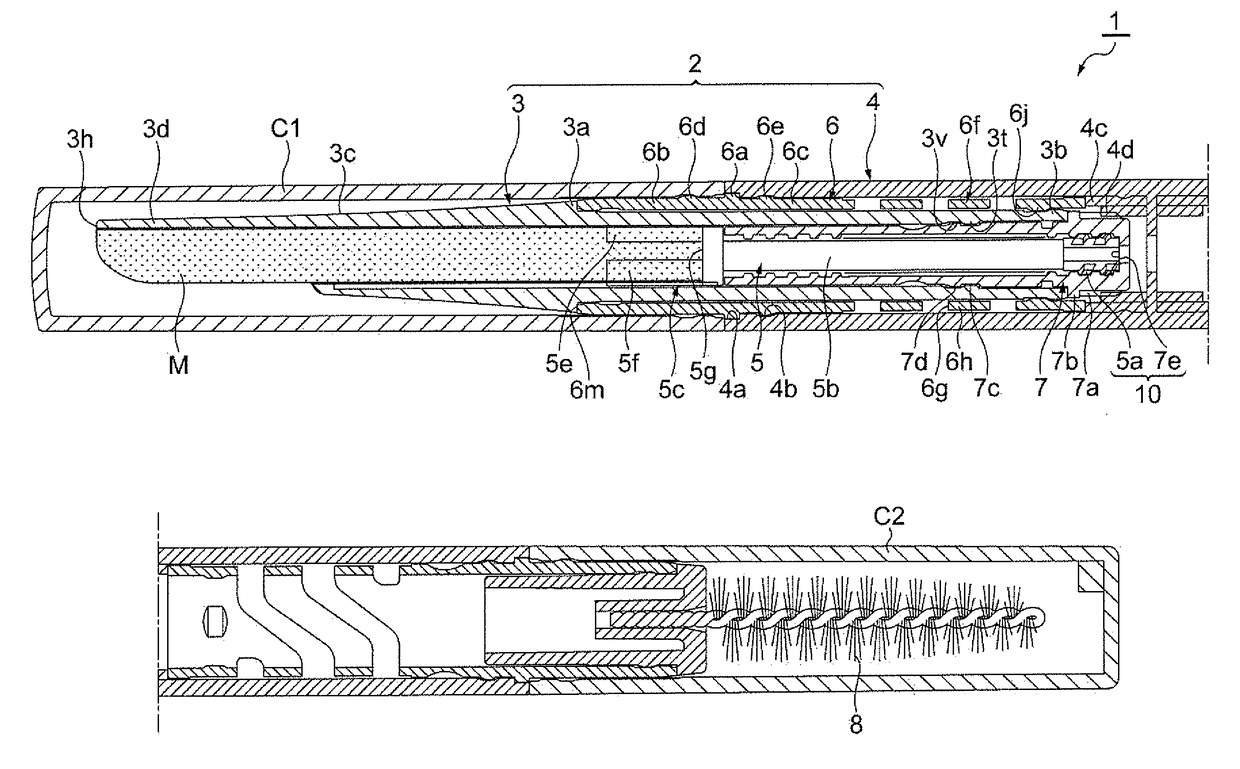
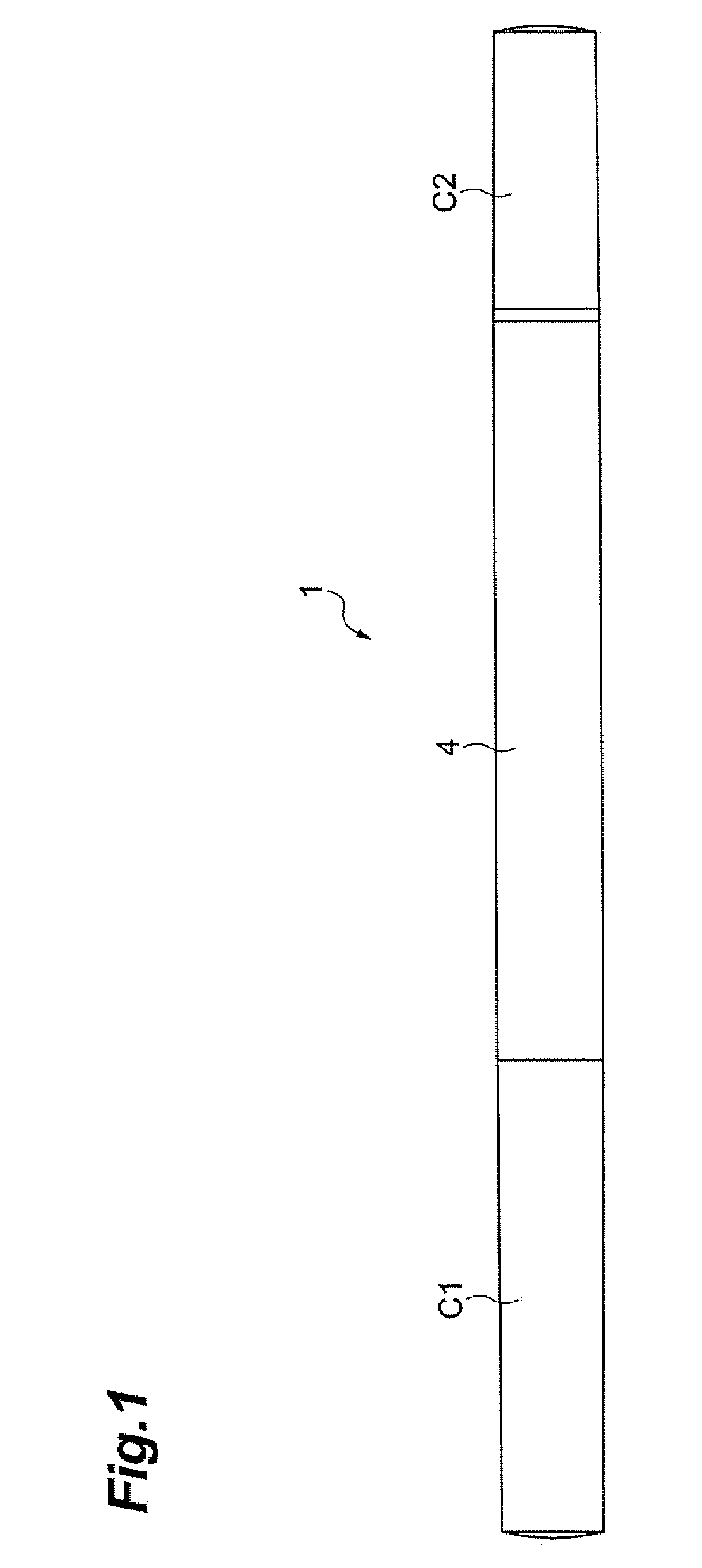
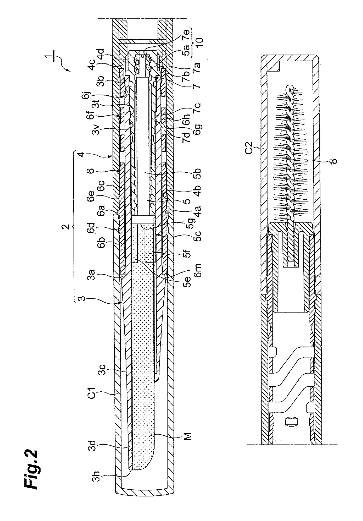
[0025]As illustrated in FIGS. 1 and 2, a stick-shaped cosmetic material dispensing container 1 (also referred to herein as “cosmetic dispensing container” or “container”) has a shape of a thin elongated cylindrical stick, for example, a writing instrument, as an overall shape. Further, the cosmetic dispensing container contains a stick-shaped cosmetic material M (also referred to herein as a “cosmetic stick M”) covered by a cap Cl. In the cosmetic dispensing container 1, a user can apply make-up using the cosmetic stick M immediately when the cap C1 is removed. As an example, the cosmetic stick M comprises eyebrow make-up and the cosmetic dispensing container 1 is an eyebrow make-up dispensing container.

[0026]For example, the cosmetic dispensing container 1 includes a cylindrical container 2 that includes a tip cylinder 3 that constitutes a container front portion or a dispensing portion and a container main body 4 constituting a container rear portion; a moving body 5 that is acco...

second embodiment

[0059]As described above, in the cosmetic dispensing container the concave portion 23j which extends in the axial direction is formed on the inner peripheral surface of the tip cylinder 23; and the convex portion P4 which extends in the axial direction and is held by the concave portion 23j is formed on the outer peripheral surface of the cosmetic stick P. The width D of the portion of the convex portion P4 entering the concave portion 23j when viewed from the front side is larger than the width E of the opening portion 23j3 of the concave portion 23j when viewed from the front side.

[0060]Accordingly, when a force is applied to the cosmetic stick. P in a direction (upward direction in FIG. 9) of detachment of the cosmetic stick P from the concave portion 23j, detachment of the convex portion P4 from the concave portion 23j and breakage of the cosmetic stick P can be reliably reduced by bringing the outside surfaces P42 of the convex portion P4 into contact with the inside surfaces ...


PUM


Abstract

A stick-shaped cosmetic material appears or disappears from a front end of the tip cylinder along with the advance or retract of the moving body, a concave portion extends to a holding portion on an inner peripheral surface of the tip cylinder, a convex portion held by the concave portion is formed on an outer peripheral surface of the stick-shaped cosmetic material, the shape of the stick-shaped cosmetic material when viewed from the front side is formed so as to be tapered as being separated from an opposing portion to the holding portion, and a width of the opposing portion of the stick-shaped cosmetic material when viewed from the front side is substantially the same as a width of the holding portion when viewed from the front side.

Description

CROSS-REFERENCE TO RELATED APPLICATION[0001]This application is based upon and claims the benefit of priority from Japanese Patent Applications No. 2017-083739, filed on Apr. 20, 2017, and No. 2017-119834, filed on Jun. 19, 2017, the entire contents of which are incorporated herein by reference.BACKGROUNDField[0002]The present disclosure relates to a stick-shaped cosmetic material dispensing container which dispenses a stick-shaped cosmetic material.Related Art[0003]As a stick-shaped cosmetic material dispensing container of the related art, a container described in Japanese Unexamined Patent Publication No. 2001-218621 has been known. Japanese Unexamined Patent Publication No. 2001-218621 describes a stick-shaped cosmetic material dispensing container which includes a tip cylinder accommodating a stick-shaped cosmetic material; and a container main body fitted rotatably to the tip cylinder. In the stick-shaped cosmetic material dispensing container, the stick-shaped cosmetic materi...

Claims


Application Information

Patent Timeline
Patent Type & Authority Applications(United States)
IPC IPC(8): A45D40/20A45D40/06A46B9/02
CPCA45D40/205A45D40/065A46B9/021A45D2034/007A45D2040/208A45D2040/201A46B2200/1046A45D40/06A45D2040/0012
Inventor SASAKI, ARATA
Owner TOKIWA CORP
Why Eureka
Try Eureka