Tactical sight for a semi-automatic hand gun

a semi-automatic handgun and sight technology, applied in the field of semi-automatic handguns, can solve the problems of reducing the ability to fully see the target, reducing the time necessary to locate the front sight, and reducing the ability to see the threat about the peripheral parts of the sight, so as to reduce the obstruction of the sight, direct and focus the user's sight quickly

Inactive Publication Date: 2007-10-18
WARREN SCOTT M
View PDF24 Cites 29 Cited by
  • Summary
  • Abstract
  • Description
  • Claims
  • Application Information

AI Technical Summary

Benefits of technology

[0009] In accordance with the present invention, provided is a rear gun sight for use in connection with a tactical semi-automatic handgun which includes configurations that minimize sight obstructions and that quickly direct and focuses the user's sight to the sight line and front sight.
[0010] More particularly, a sight according to the present invention is configured to maximize the visual ability of the user to see past the rear sight for both target acquisition and front sight location by minimizing the cross-sectional configuration of the sight. In this respect, a rear surface minimizing design is incorporated on either side of the notch. This minimizing design greatly reduces the visual obstructions near the notch, so that the user can more quickly obtain target acquisition. The user's vision is now directed by the flow of the minimizing design and the resulting narrowness of the sight top to the sight line and front sight. Essentially the upper portion of the gun sight contains only the notch.

Problems solved by technology

Traditional rear sights are typically square, boxy and include sharp corners.
This lengthens time necessary to locate the front sight.
In addition, the large rectangular rear portion of prior art gun sights acts as an obstruction, which reduces the ability to see the threat about the peripheral portions of the sight.
When handguns are fired, typically at an arm's length from the user, a large bulky rear sight reduces the ability to fully see the target, especially when it is small and / or distant or when the user needs to distinguish if the threat is armed.
This, in addition to the user searching a large top edge of the sight to locate the front sight, takes significant time under tactical, life threatening circumstances and therefore disadvantageously increases the time necessary for target acquisition and sight alignment.
Prior art gun sights also include eye distracting configurations and textures on the rear facing surface of the sight which produces time consuming distractions to the user's eye.
In this respect, sharply square outer corners have a tendency to draw the user's eye to the corners of the gun sight, momentarily distracting the user, while the user is attempting to locate the front sight and align it in the notch of the rear sight.
While some prior art sights such as Swenson, utilize textures to reduce glare, the textures tend to produce an eye distraction, disadvantageously increasing the threat acquisition time and sight alignment time.
Semi-circular notches are difficult to align since there are no sidewalls to reference against the sides of the front sight.
However, while prior art rectangular notches provide better reference based on the side edges, it has also been found that square corners at the bottom of the notch detract the user's eye in that the eye is drawn to the sharp corners.
Another problem with the prior art sight relates to the length of the notch.
Notches which have a long length produce more of an obstruction to the sight line which increases the amount of time necessary for target acquisition and for finding the front sight.
Turning to the width of the notch, rear notches which are substantially wider than the width of the front sight make it difficult to center the front sight within the notch which also adds to the time necessary for target acquisition.
Further, due to the adverse conditions, the firearm can be dropped and / or be engaged against the terrain and / or obstacles.

Method used


Image

  • Tactical sight for a semi-automatic hand gun
  • Tactical sight for a semi-automatic hand gun
  • Tactical sight for a semi-automatic hand gun

Examples


Embodiment Construction

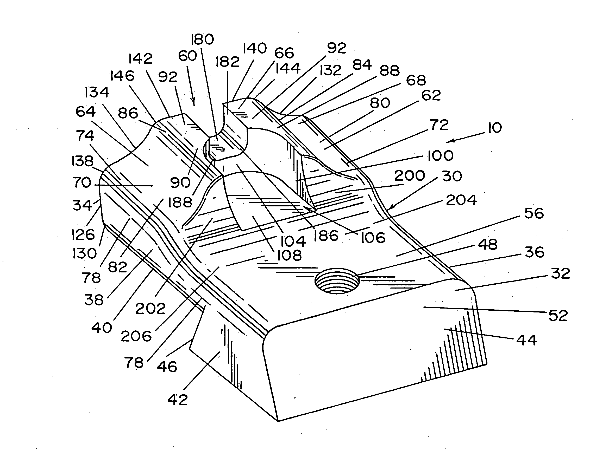
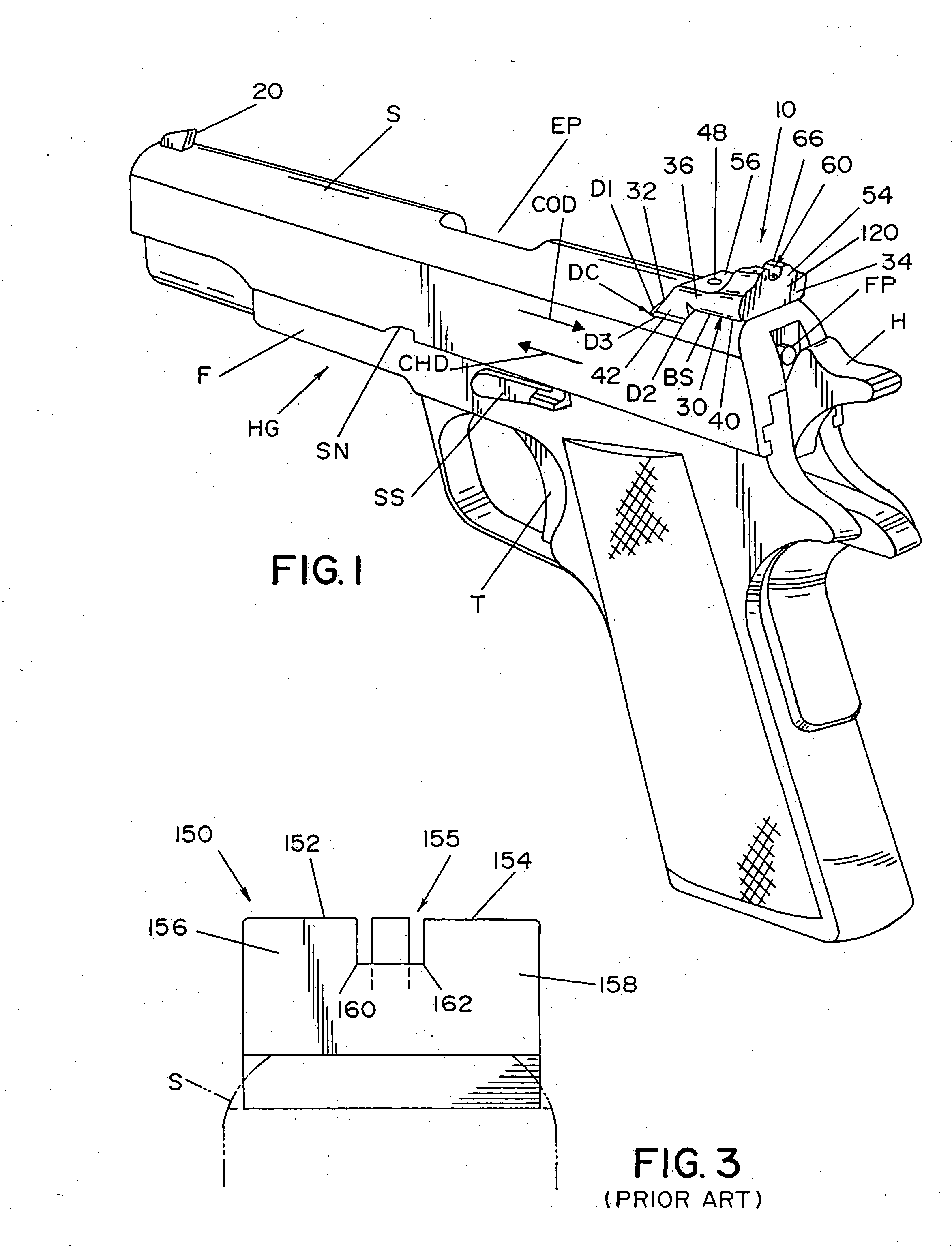
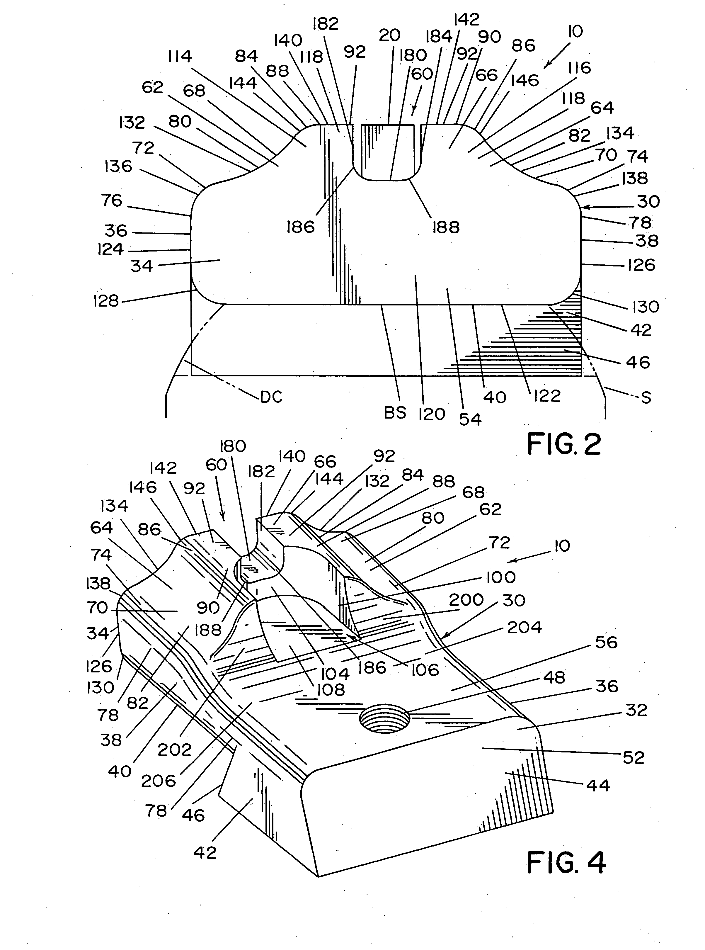
[0030] Referring now in greater detail to the drawings wherein the showings are for the purpose of illustrating preferred embodiments of the invention only, and not for the purpose of limiting the invention, FIG. 1 shows a semi-automatic handgun HG and slide S with a rear tactical sight 10 and a front tactical sight 20 mounted thereon. A dovetail cut DC and a base surface BS are machined into a portion of the top surface of slide S which allows rear sight 10 to be rigidly secured to slide S and to be precisely oriented relative to a barrel (not shown) for firing accuracy. However, while a dovetail may be preferred, it is not necessary for the invention of this application.

[0031] Slide S moves relative to a frame F of handgun HG rearwardly in a cocking direction COD to extract and eject a spent cartridge (not shown) from the barrel and to simultaneously cock a hammer H. When this rearward motion is complete, slide S then moves forwardly in a chambering direction CHD to chamber a new...


PUM


Abstract

A rear tactical sight for a handgun having a barrel with a barrel axis. The sight including a base extending in a longitudinal direction parallel to the barrel axis. The base having a front and an oppositely facing back with sides extending in the longitudinal direction between the front, the back and a bottom. The sight further including an upwardly opened notch joined to the base and spaced above the base bottom which at least partially defines boundaries of a sight line for the sight and a pair of side walls spaced on either side of the sight line each having outer surfaces that are opposite to one another and which extend upwardly from the base sides. The outer surfaces being substantially symmetrical to one another and each including a first arcuate surface extending upwardly and inwardly from a corresponding one of the base sides respectively and a second arcuate surface extending inwardly and upwardly from the first surface.

Description

[0001] This application is a Continuation-In-Part application of patent application Ser. No. 10 / 228,100 filed on Aug. 27, 2002.[0002] The present invention relates to the art of gun sights and, more particularly, to a gun sight for a semi-automatic handgun used for tactical applications, where quick target acquisition and quick sight alignment are critical and wherein the sight is subjected to many adverse conditions and situations. Incorporation by Reference [0003] The present invention relates to a gun sight for a semi-automatic handgun for tactical applications. Such gun sights are known in the art and are generally shown and described in Flubacher U.S. Pat. No. 6,216,351 which is incorporated by reference herein as background information illustrating a front and rear sight for a semi-automatic handgun including the interengagement between the sight and the slide of the handgun. Barringer 1,363,553; U.S. Pat. No. Waki U.S. Pat. No. 5,822,872 and Hollenbach U.S. Pat. No. 6,035,539...

Claims


Application Information

Patent Timeline
Patent Type & Authority Applications(United States)
IPC IPC(8): F41G1/00F41G1/10
CPCF41G1/10
Inventor WARREN, SCOTT M.
Owner WARREN SCOTT M
Why Eureka
Try Eureka