Device and method for blowing down and measuring the back pressure of chemical reactor tubes

a back pressure measurement and chemical reactor technology, applied in fluid tightness measurement, digital computer details, instruments, etc., can solve the problems of high packing density, adversely affecting the efficiency of reaction, and high labor intensity of devices and methods used in the past, so as to improve the ability to measure the back pressure in tubes, less labor intensity, and more accurate

Inactive Publication Date: 2002-09-19
TUBEMASTER INC
View PDF0 Cites 21 Cited by
  • Summary
  • Abstract
  • Description
  • Claims
  • Application Information

AI Technical Summary

Benefits of technology

0007] The present invention provides a device and method that improves the ability to measure the back pressure in tubes, making the process much more accurate, faster, less labor intensive, more efficient, safer, less dependent on the skill of the worker, and yielding more accurate and more useful results. In a preferred embodiment, the measuring device uses an inflatable, conforming seal, which provides a good seal between the measuring device and the chemical re

Problems solved by technology

However, in reality, there is a variation in packings which adversely affects the efficiency of the reaction by providing for different residence times in different tubes.
High back pressures can also indicate problems other than high packing density, such as dust, fines, obstructions in tubes, and the presence of foreign material.
Low back pressures can also indicate problems other than low packing density, such as bridging.
However, the devices and methods that have been used in the past have been labor intensive and time consuming, their accuracy has depended largely upon the skill of the operator, and they have yielded data that is not readily usable.
Weldments at the top of the tube can

Method used


Image

  • Device and method for blowing down and measuring the back pressure of chemical reactor tubes
  • Device and method for blowing down and measuring the back pressure of chemical reactor tubes
  • Device and method for blowing down and measuring the back pressure of chemical reactor tubes

Examples


Embodiment Construction

:

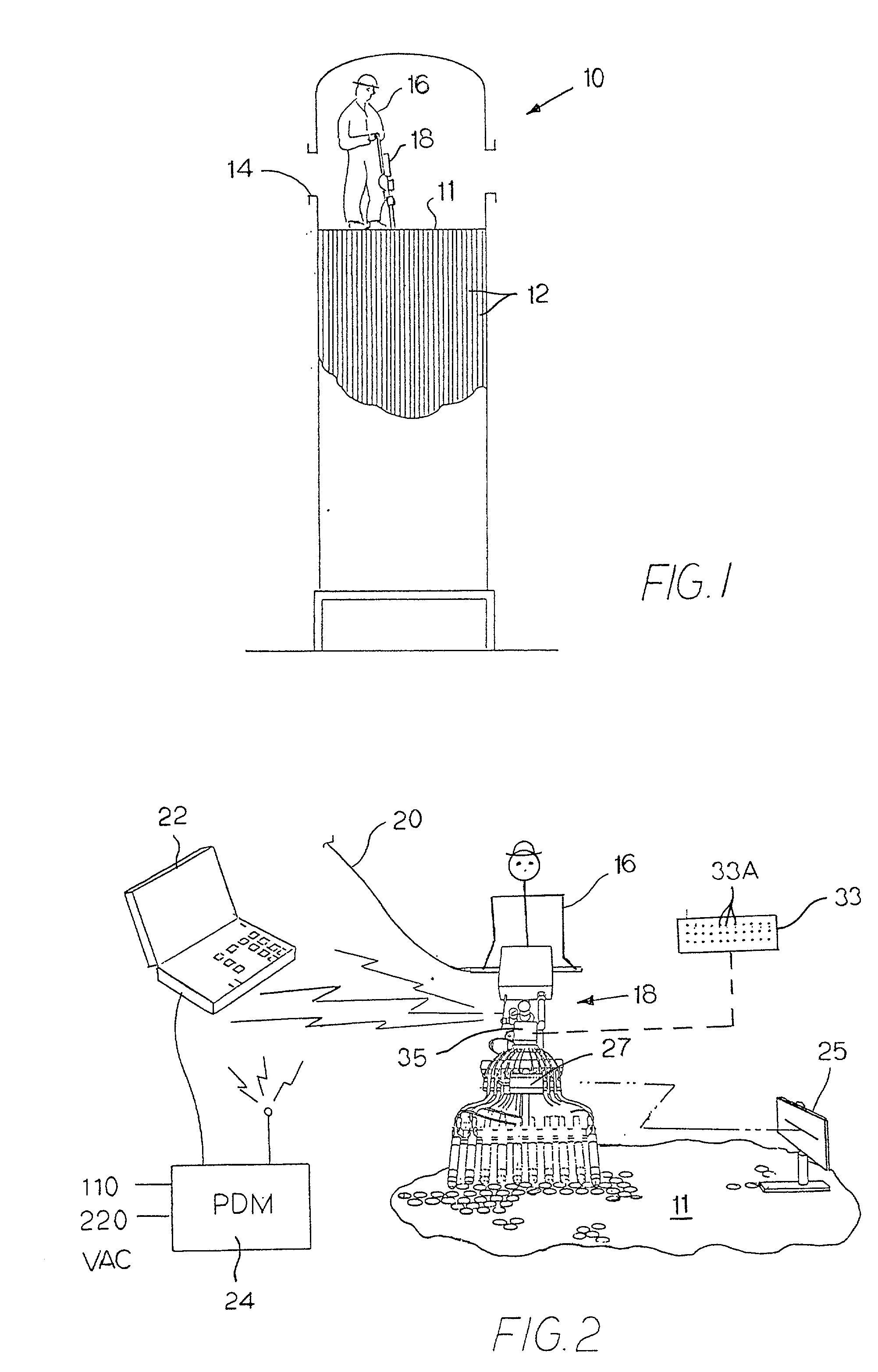
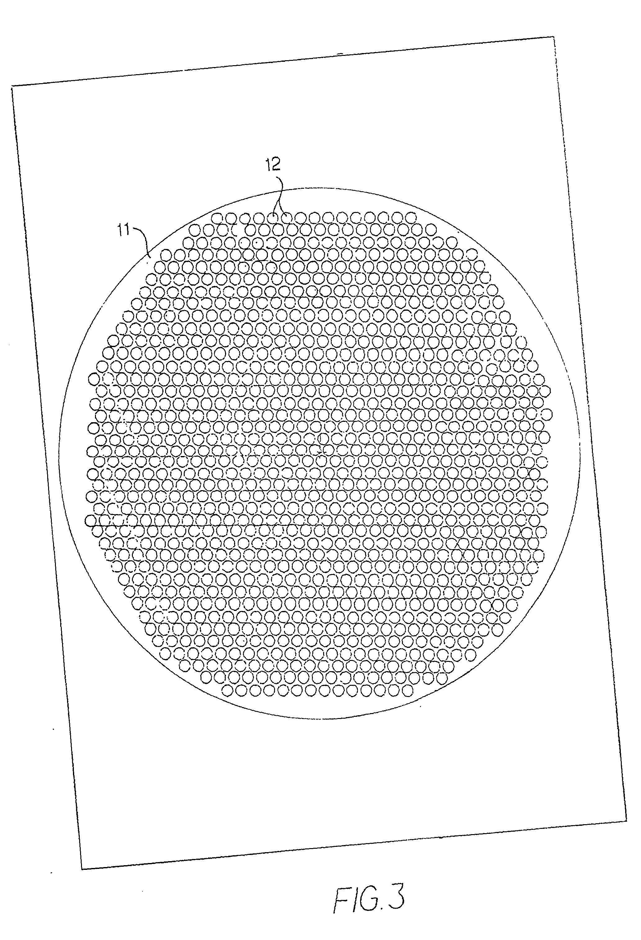
[0038] FIG. 1 is a schematic view of a chemical reactor 10, including a plurality of tubes 12, which hold catalyst. The tubes 12 extend downwardly from an upper plate (or tube sheet) 11 and are open on the bottom, except for clips (not shown), which may be used to prevent the catalyst from falling out the bottom of the tubes. A manway 14 provides access for workers to get into the reactor 10. A worker 16 is shown inside the reactor 10, measuring the back pressure in the catalyst tubes 12. In other reactors, the top may be fully removable, providing improved access.

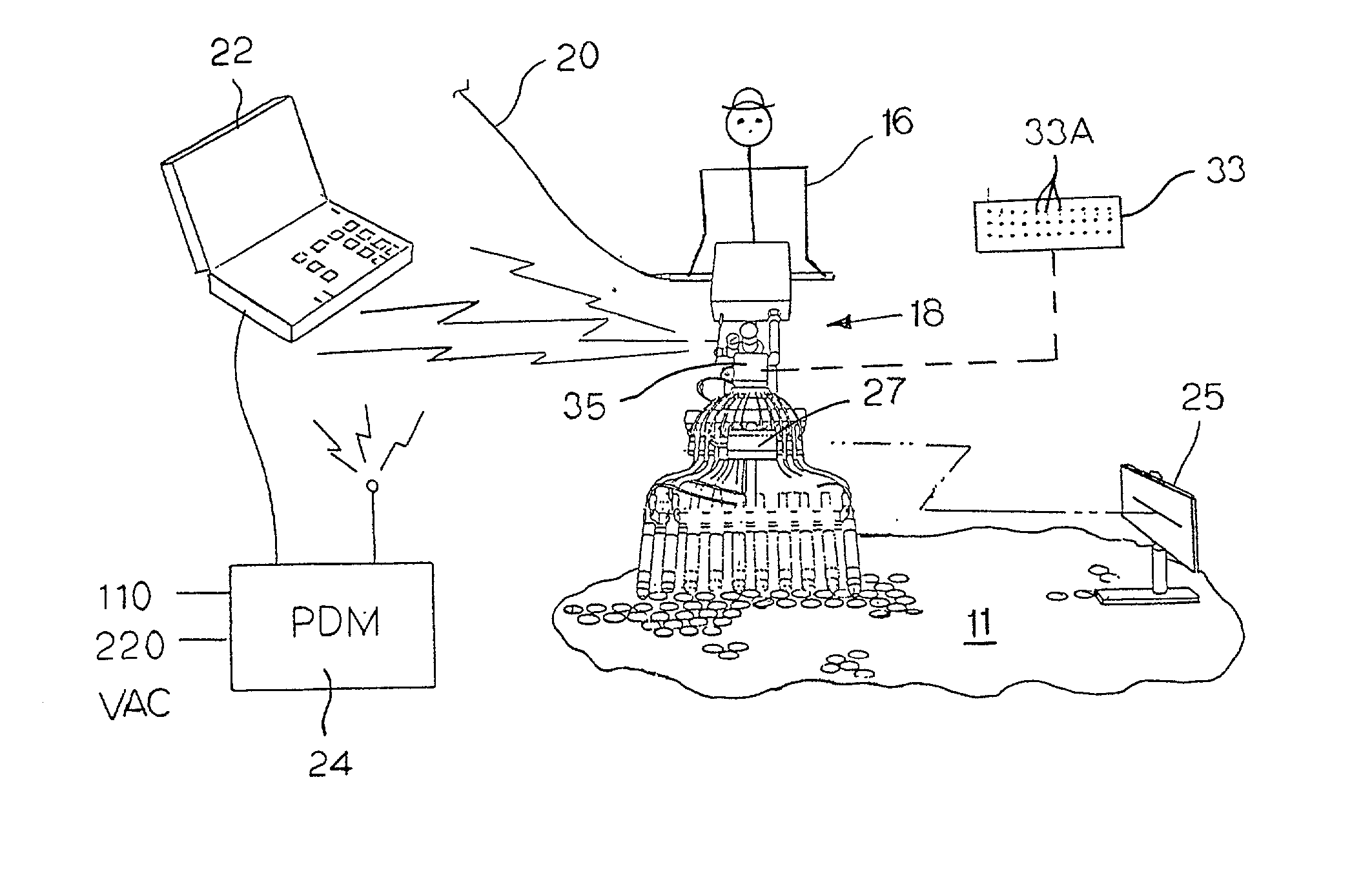
[0039] FIG. 2 shows the worker 16 standing on the plate 11 and operating a hand-held wand 18, which measures the back pressure in the tubes 12. When the wand 18 is inserted into a bank of ten tubes in the plate 11, it is self-supporting and rests on the plate 11. The wand 18 is connected to a gas line 20 and communicates with a remote computer 22 through a power and data module 24. In this particular embodiment, the gas l...


PUM


Abstract

A device for measuring the back pressure in chemical reactor tubes includes many automated features. Inflatable tube seals may be automatically inflated. The device may measure several tubes at once. It may transmit data electronically to a remote computer for analysis and graphic display.

Description

[0001] This application claims priority from and incorporates by reference U.S. Provisional application S. No. 60 / 276,780, filed Mar. 16, 2001 and U.S. Provisional application S. No. 60 / 314,859, filed Aug. 24, 2001.BACKGROUND[0002] The present invention relates to tubes in chemical reactors, and, in particular, to a device and method for measuring the back pressure in the tubes and for blowing dust out of the tubes.[0003] Many chemical reactors use a catalyst as part of the reaction process. The catalyst material frequently is coated onto or contained in a substrate which is packed in tubes within the reactor. The reactants flow through the tubes and out the open ends of the tubes, reacting in the presence of the catalyst to form the products of the reaction. It is desirable to be able to measure the packing of catalyst within the tube in order to determine whether the tube will function properly. Ideally, the catalyst packing in all the tubes will be very close to the same. However...

Claims


Application Information

Patent Timeline
IPC IPC(8): G01M99/00B01J8/00B01J8/06G01L7/00
CPCB01J8/008B01J8/06B01J2208/00539B01J2208/00805G01L9/00
Inventor JOHNS, CLIFFORD L.SYMPSON, DANIEL D.
Owner TUBEMASTER INC
Why Eureka
Try Eureka