Current rectifier assembly for rotating electrical machines, in particular motor vehicle alternator

a current rectifier and electrical machine technology, applied in the direction of magnetic circuit rotating parts, magnetic circuit shape/form/construction, windings, etc., can solve the problem of not allowing the increase of cooling capacity

Inactive Publication Date: 2003-09-25
VALEO EQUIP ELECTRIC MOTEUR
View PDF2 Cites 32 Cited by
  • Summary
  • Abstract
  • Description
  • Claims
  • Application Information

AI Technical Summary

Benefits of technology

[0044] The rectifying equipment of the invention has the further advantage that it is easy to assemble. In this connection, assembly is carried out by stacking the various components through the top of the machine, that is to say from the outside. This enables the rear bearing to be assembled before it is fitted on the rest of the machine. Similarly, the diodes are inserted in the same direction with the diode tails all pointing upwards, which makes it possible to use only a single soldering means and eliminates transfer of parts. In addition, the diodes are positioned in such a way that there is only a single soldering plane. The positioning of the parts has been designed in such a way as to have the heaviest parts as close as possible to the fastenings, thereby limiting their cantilever. This leads to improved reliability, and enables vibrations and resonant frequencies to be higher, so as to avoid points of magnetic noise due to the magnetic forces generated by the machine.

Problems solved by technology

This rectifying equipment has the disadvantage that it does not allow cooling capacity to be increased to enable it to be used in alternators of higher power while at the same time giving an acceptable size.

Method used


Image

  • Current rectifier assembly for rotating electrical machines, in particular motor vehicle alternator
  • Current rectifier assembly for rotating electrical machines, in particular motor vehicle alternator
  • Current rectifier assembly for rotating electrical machines, in particular motor vehicle alternator

Examples


Embodiment Construction

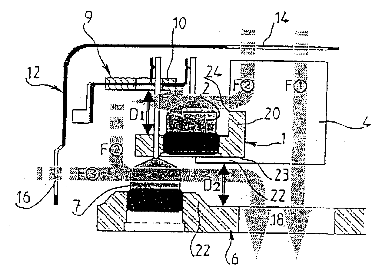
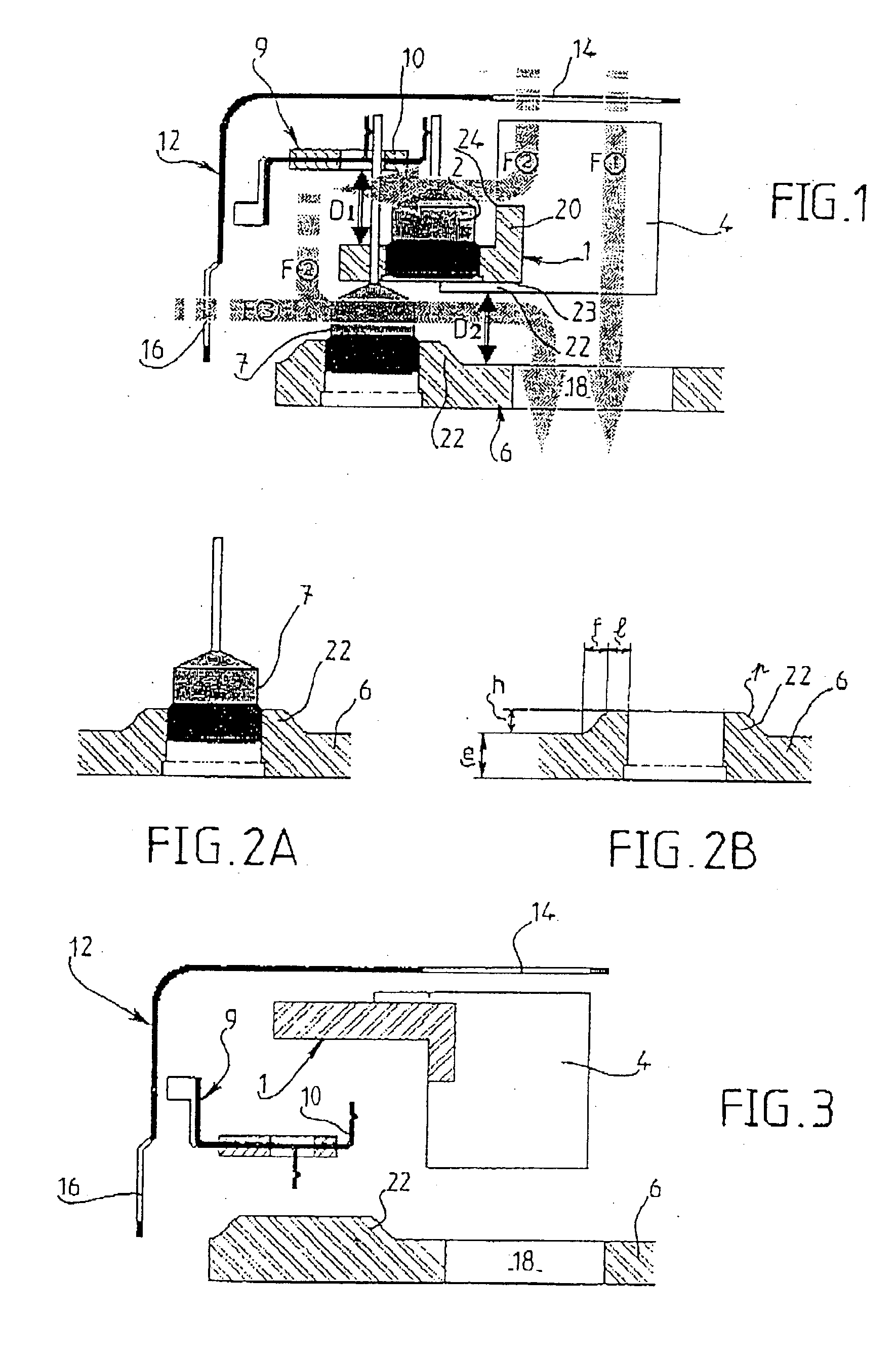
[0024] FIG. 1 is a diagrammatic view of a current rectifying equipment, for example for a polyphase alternator, the general structure of which is known per se, for example from French patent No. 2 687 861 and European patent 055 15 259.

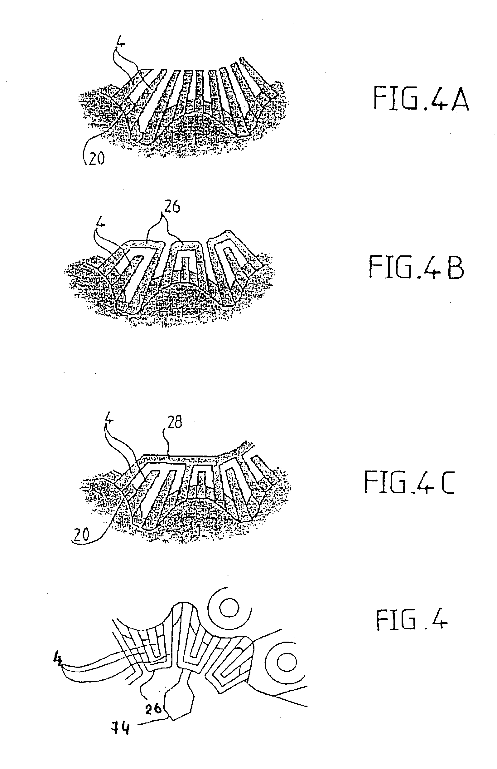
[0025] In FIGS. 1 and 4, the rectifying equipment comprises a support 1, which is of metal in this case with a plurality of positive diodes 2, and which is in the form of a plate which carries on its front face, oriented towards the axis of rotation (not shown) of the machine, cooling fins 4 which extend towards the said axis. A function of the metallic support, which in this case is basically of aluminium, is to provide cooling for the diodes, and it is accordingly called the positive radiator. The radiator 1 is located at a predetermined axis distance D2 towards the axis of the machine, above the rear bearing 6, in the bore of which a plurality of negative diodes 7 are force-fitted. The rear bearing 6 is of metal and in the present example it is aga...


PUM


Abstract

The invention relates to current rectifying equipment for rotary electrical machines having a rear bearing, of the type comprising a plurality of positive diodes (2) supported by a support (1) in the form of a plate, a plurality of negative diodes (7) supported by the rear bearing (6) of the machine, a device (9) for connecting the positive and negative diodes together, and means for generating a forced axial stream of a coolant fluid, the support (1) for the diodes carrying cooling fins (4) which extend in the said axial stream (F1) of the coolant fluid in the radial direction of the machine. The equipment is characterised in that it includes means for effecting mixed cooling of the support for the negative diodes by convection and conduction. The invention can be used for alternators for motor vehicles.

Description

[0001] This invention relates to current rectifying equipment for rotary electrical machines, in particular alternators for motor vehicles, of the type comprising a stator and a rotor mounted inside the stator, the equipment comprising a plurality of positive diodes supported by a support in the form of a plate, a plurality of negative diodes supported by a support in the form of a plate, such as the rear support bearing for the rotor of the machine, a connecting device for electrically interconnecting the positive and negative diodes, and means for generating a forced flow of a coolant fluid flowing in the axial direction of the machine; the support for the positive diodes carrying, on its front face oriented towards the axis of the machine, cooling fins which extend in the axial flow of the coolant fluid in the radial direction of the machine. In a known way, the rotor, through its shaft, is mounted for rotation in front and rear bearings, each of which carries for this purpose a ...

Claims


Application Information

Patent Timeline
Patent Type & Authority Applications(United States)
IPC IPC(8): H02K9/04H02K9/06H02K9/28H02K11/04H02K19/36
CPCH02K11/046H02K9/06H02K11/05H02K9/10
Inventor AESCHLIMANN, MICHAELARRIGHI, SEBASTEIENFAVEROLLE, PIERREHEVIA, THIERRYSCHULTE, DIRKMASRIERA, SERGE
Owner VALEO EQUIP ELECTRIC MOTEUR
Why Eureka
Try Eureka