
System and method for implementing shared memory regions in distributed shared memory systems
a shared memory and distributed memory technology, applied in the field of memory mapping scheme, can solve the problems of data loss, increased data vulnerability, and detrimental effect on storage device performan
- Summary
- Abstract
- Description
- Claims
- Application Information
AI Technical Summary
Problems solved by technology
Method used
Image

Examples
Embodiment Construction
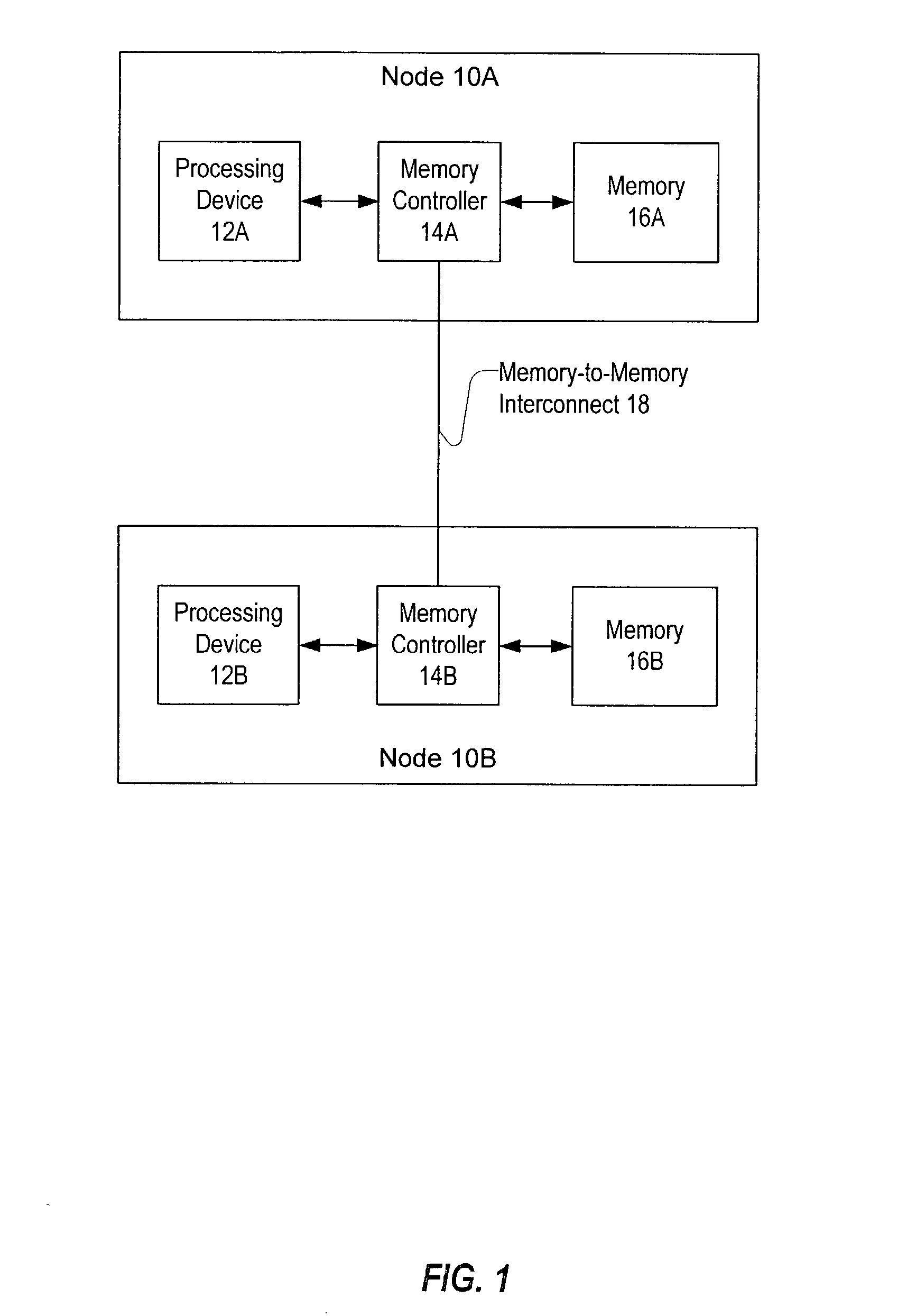
[0032] FIG. 1 shows one embodiment of a distributed shared memory (DSM) system. Two nodes, node 10A and node 10B, are illustrated. In some embodiments, nodes 10A and 10B may each be configured as a storage controller (e.g., an array controller or a disk drive controller). Node 10A includes a processing device 12A, a memory controller 14A, and a memory 16A. Similarly, node 10B includes a processing device 12B, a memory controller 14B, and a memory 16B. Note that other embodiments may include significantly more nodes 10 than are illustrated in FIG. 1. Additionally, note that a node may include other devices that are not shown in FIG. 1. For example, each node may include one or more interfaces to other interconnects that couple that node to devices such as another computer system, a storage system, etc. Throughout this disclosure, devices identified by the same reference numeral followed by a unique alphabetic identifier (e.g., nodes 10A and 10B) may be collectively referred to by the...
PUM
 Abstract
Description
Claims
Application Information