Liquid delivering apparatus

a liquid delivery and apparatus technology, applied in the direction of piston pumps, electric/electrostrictive devices, printing, etc., can solve the problems of higher cost to obtain an apparatus suitable for high-voltage use, and achieve the effects of increasing the volume of the liquid chamber, increasing the pressure of the liquid in the chamber, and reducing the pressure of the liquid in the liquid chamber

Active Publication Date: 2005-01-20
BROTHER KOGYO KK
View PDF1 Cites 1 Cited by
  • Summary
  • Abstract
  • Description
  • Claims
  • Application Information

AI Technical Summary

Benefits of technology

[0011] In the liquid delivering apparatus in accordance with the present invention, when an electric voltage is applied to the restrictor sheet provided on one side of the piezoelectric sheet, and each of the second electrodes that is provided on the other side of the piezoelectric sheet and cooperates with a corresponding one of the restrictive portions of the restrictor sheet to sandwich a corresponding one of the active portions of the piezoelectric sheet, an electric field is produced in a direction substantially parallel to the direction of polarization of the piezoelectric sheet. Owing to this electric field, the one active portion of the piezoelectric sheet is deformed, by piezoelectric effect, in a direction substantially parallel or perpendicular, to the direction of polarization thereof, and the one restrictive portion of the restrictor sheet restricts the deformation of the one active portion. Consequently, the respective portions of the piezoelectric sheet and the restrictor sheet are deformed or curved in a direction away from the liquid chamber, so that the volume of the liquid chamber is increased and the pressure of the liquid accommodated in the

Problems solved by technology

In addition, in the case where the ink is ejected in the above-explained “fill-after-fire” manner, a considerably high voltage is ne

Method used


Image

  • Liquid delivering apparatus
  • Liquid delivering apparatus
  • Liquid delivering apparatus

Examples


Embodiment Construction

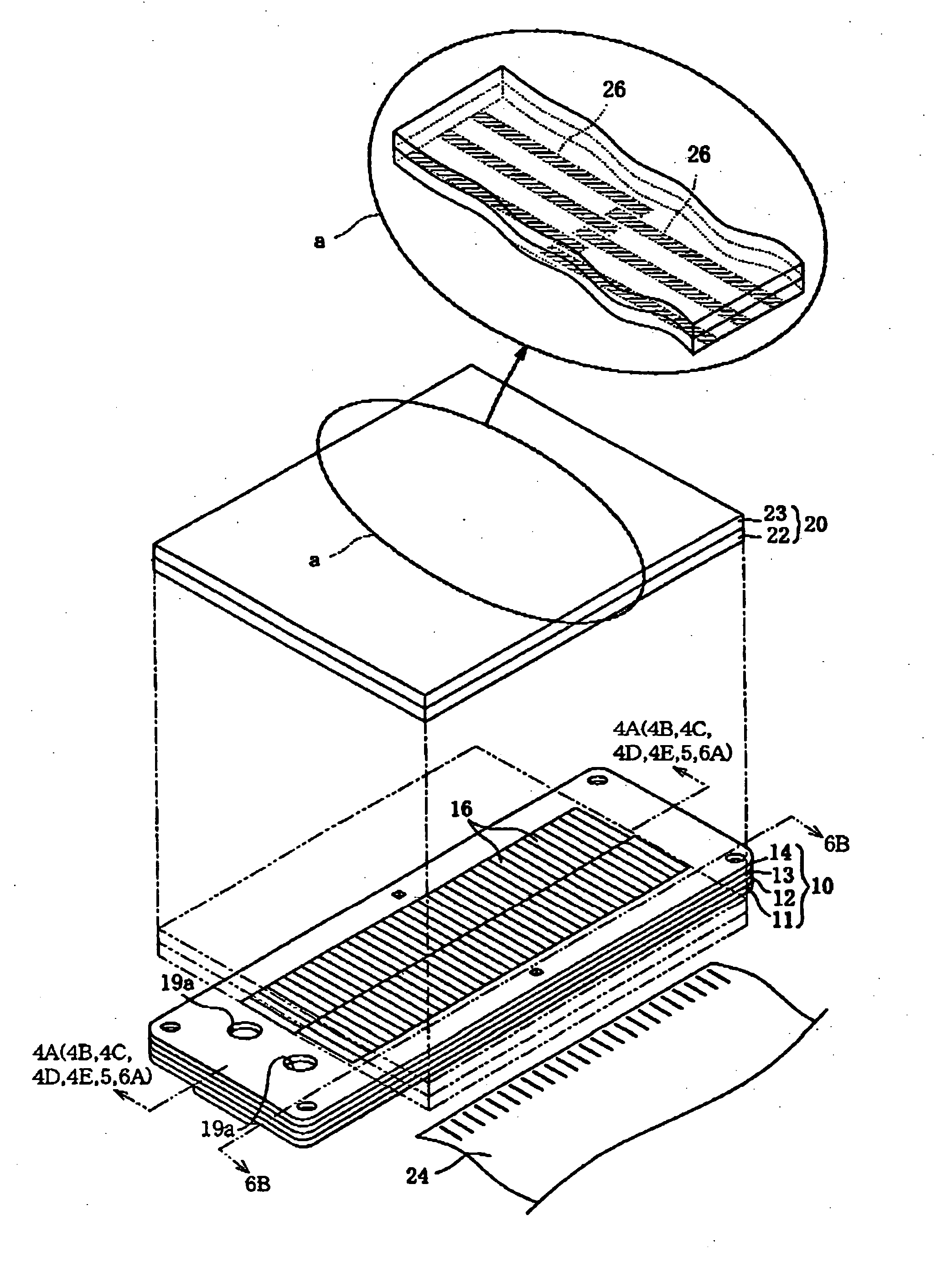
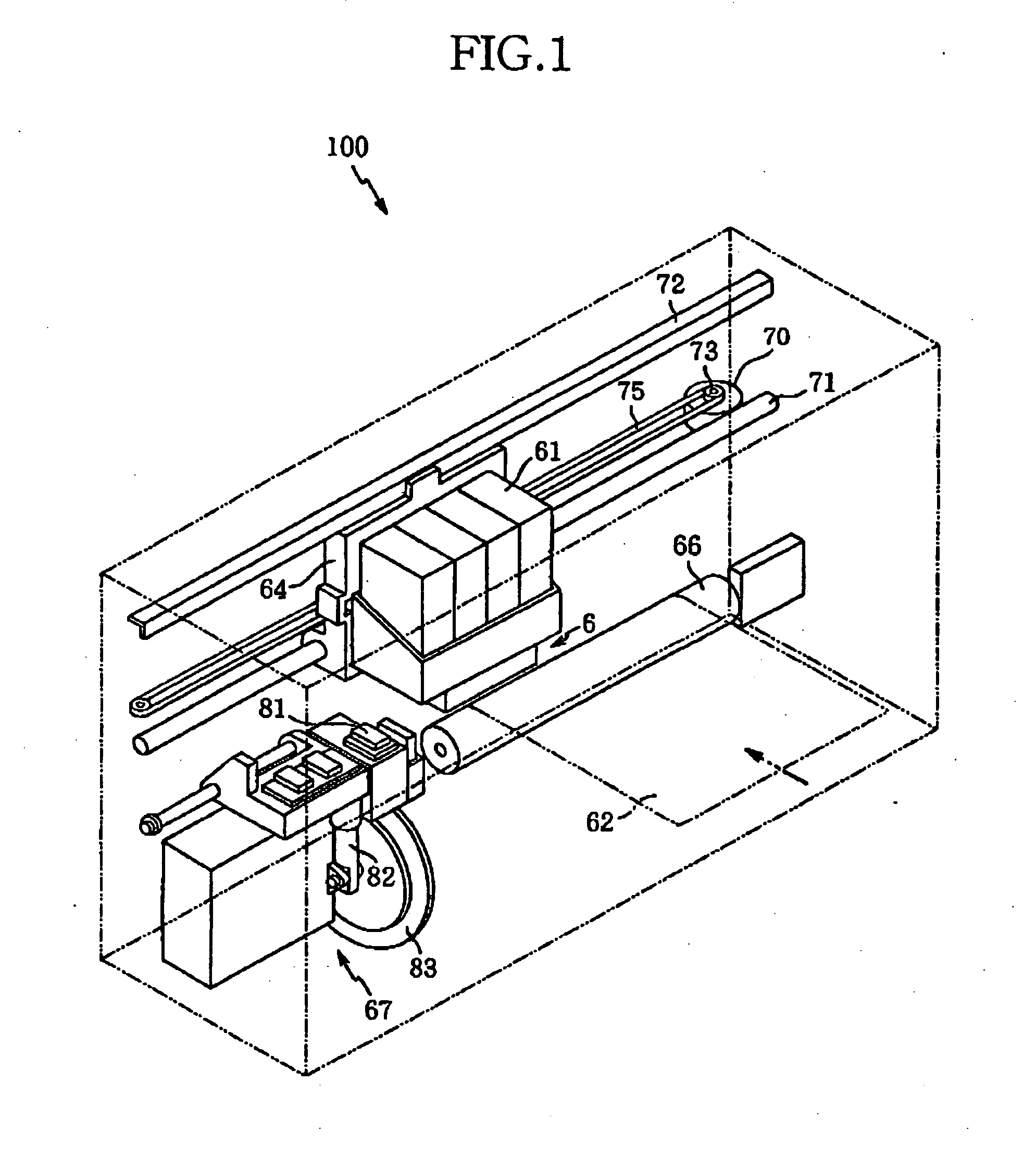
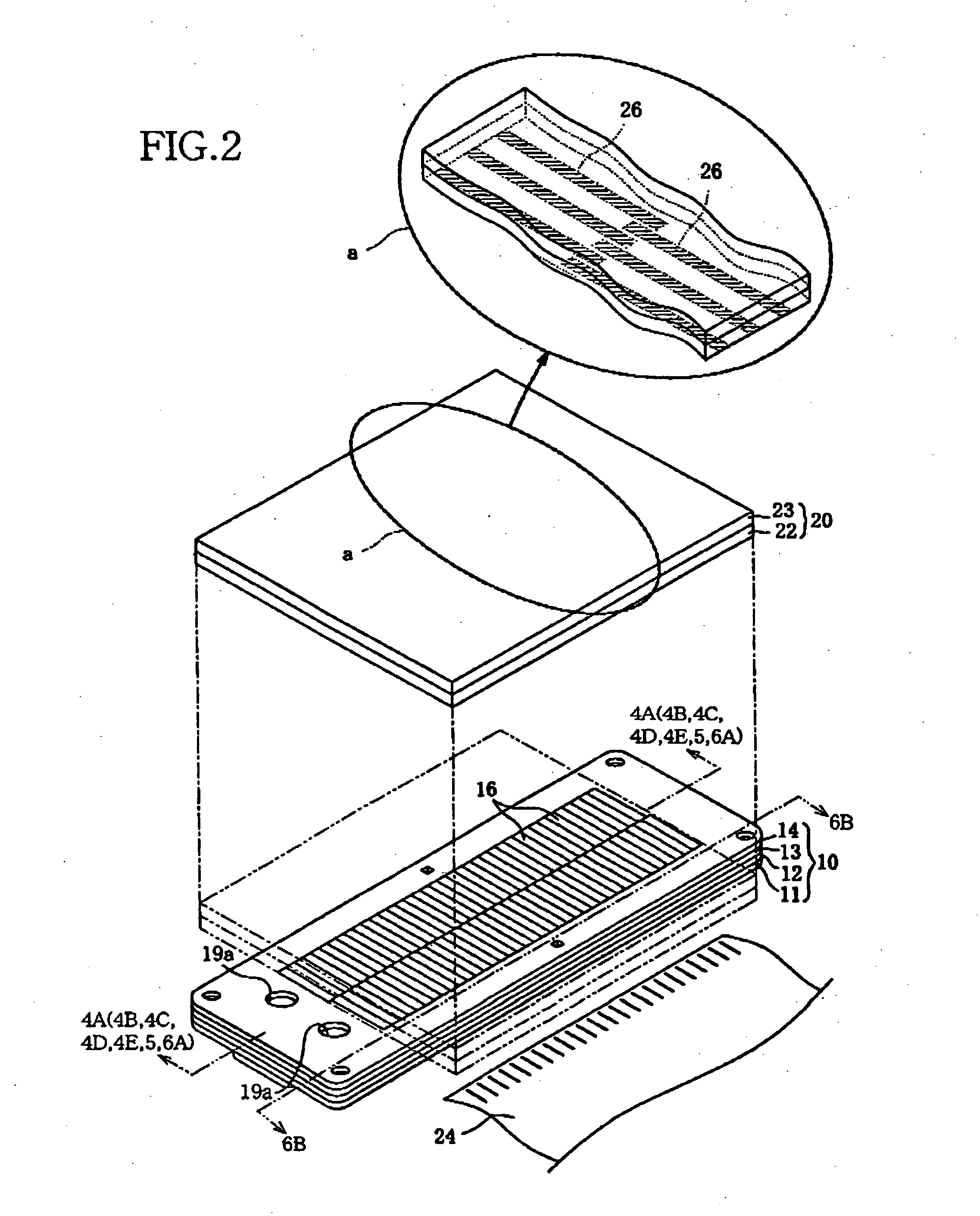
[0024] Hereinafter, there will be described a preferred embodiment of the present invention by reference to the drawings. FIG. 1 shows an ink jet recording apparatus 100 employing a piezoelectric ink jet recording head 6 in accordance with the present invention. First, the ink jet recording apparatus 100 is briefly described. The piezoelectric ink jet recording head 6 is for ejecting, from each of a plurality of ink ejection nozzles 54 (FIG. 3), a droplet of ink toward a sheet of paper 62 as a sort of recording medium, and thereby recording an image on the sheet of paper 62. The recording head 6 is mounted, together with ink cartridges 61, on a carriage 64, such that the recording head 6 faces downward. The recording head 6 will be described in detail, later.

[0025] The carriage 64 on which the ink jet recording head 6 is mounted is secured to an endless belt 75 and, when a pulley 73 is rotated forward and backward by an electric motor 70, the endless belt 75 is moved and accordingl...


PUM


Abstract

A liquid delivering apparatus including a piezoelectric sheet which is opposed to liquid chambers and is polarized in a direction of thickness thereof; a restrictor sheet which is opposed to the liquid chambers, restricts a deformation of the piezoelectric sheet, and functions as a first electrode; and second electrodes which are opposed, via active portions of the piezoelectric sheet, to restrictive portions of the restrictor sheet, respectively, and are opposed to the liquid chambers, respectively. When an arbitrary one of the active portions of the piezoelectric sheet is deformed by an electric field which is generated in a direction substantially parallel to the direction of polarization of the piezoelectric sheet, the arbitrary one of the active portions of the piezoelectric sheet and a corresponding one of the restrictive portions of the restrictor sheet are curved in a direction to increase a volume of a corresponding one of the liquid chambers.

Description

[0001] The present application is based on Japanese Patent Application No. 2003-0.197329 filed on Jul. 15, 2003, the contents of which are incorporated herein by reference. BACKGROUND OF THE INVENTION [0002] 1. Field of the Invention [0003] The present invention relates to a liquid delivering apparatus and, in particular, to such a liquid delivering apparatus employing a sheet-stacked body in which a piezoelectric sheet and a restrictor sheet are stacked on each other and which is deformed or curved in a direction to increase a volume of a liquid chamber which accommodates a liquid. [0004] 2. Related Art Statement [0005] There has conventionally been known a liquid delivering apparatus which delivers a liquid from a liquid chamber to an external location, by deforming a piezoelectric element and thereby applying a pressure to the liquid in the liquid chamber to which the piezoelectric element is opposed. An example of the liquid delivering apparatus is an ink jet recording head disc...

Claims


Application Information

Patent Timeline
IPC IPC(8): B41J2/055B41J2/045B41J2/135B41J2/14B41J2/145B41J2/15B41J2/16F04B9/00F04B43/02F04B43/04H01L41/09H01L41/23H01L41/29H01L41/39
CPCB41J2/14209B41J2202/11B41J2002/14266B41J2/14233
Inventor KOBAYASHI, KAZUOKOJIMA, MASATOMO
Owner BROTHER KOGYO KK
Why Eureka
Try Eureka